Workpiece residual stress detection method based on ultrasonic driven boring

A residual stress and detection method technology, applied in the direction of force/torque/work measuring instruments, measuring devices, instruments, etc., can solve the problems of additional cutting stress, large cutting force, uncontrollable applied force, etc., to reduce additional stress and Effects of microplastic deformation, reduced contact time, and reduced error value

Inactive Publication Date: 2017-11-17
NINGBO INST OF MATERIALS TECH & ENG CHINESE ACADEMY OF SCI
View PDF7 Cites 4 Cited by
  • Summary
  • Abstract
  • Description
  • Claims
  • Application Information

AI Technical Summary

Problems solved by technology

The residual stress detected by the blind hole method is the residual stress of the measured object itself, which requires drilling holes on the measured object to release the residual stress. This residual stress is inherent and should not be interfered or changed by the outside world. With technology, there are the following major problems in the drilling operation, which will lead to inaccurate test data
[0004] 1. When drilling, the material to be tested is in a state of plastic flow, and there is complex compressive deformation around the drill bit, which will bring additional cutting stress and cause a large detection error of residual stress at the measured point
[0005] 2. Regardless of whether manual feeding or automatic feeding is used to drill holes, the longitudinal cutting force applied by the prior art is relatively large, resulting in a relatively large residual stress reading of the measured workpiece, especially when drilling with a hand electric drill , the applied force is uncontrollable, if the force is large, the measured residual stress value will be several times or even more than the actual value
[0006] 3. The cutting force is large, it is easy to cause deformation and damage to the edge of the hole in the center of the strain rosette, and the inaccurate residual stress value will also be obtained
[0008] 5. Furthermore, since the workpiece under test and the strain rosette are connected by glue, the additional heat generated during the drilling process will cause adverse effects such as cracking of the workpiece under test and the strain rosette, resulting in a deviation between the detected residual stress value and the actual value

Method used


Image

  • Workpiece residual stress detection method based on ultrasonic driven boring
  • Workpiece residual stress detection method based on ultrasonic driven boring
  • Workpiece residual stress detection method based on ultrasonic driven boring

Examples


Embodiment Construction

[0031] Embodiments of the present invention will be described in further detail below in conjunction with the accompanying drawings.

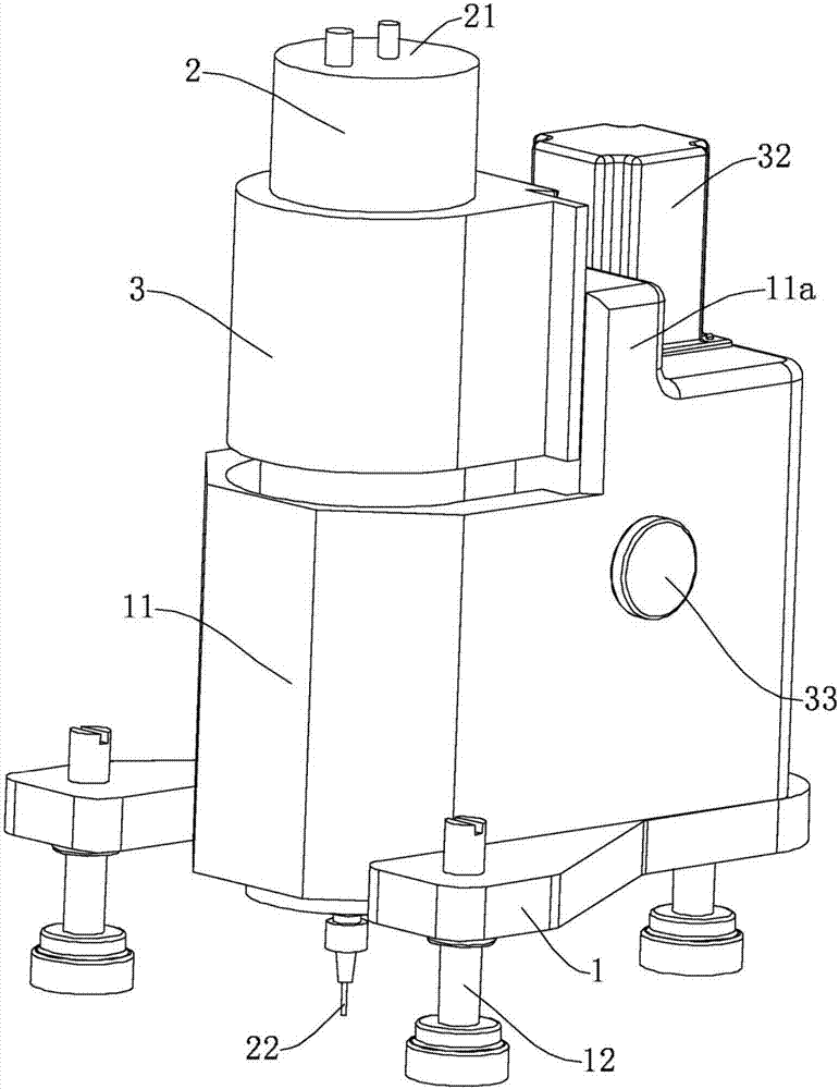
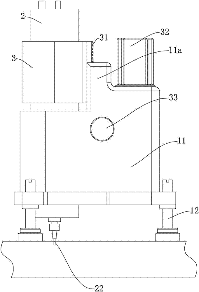
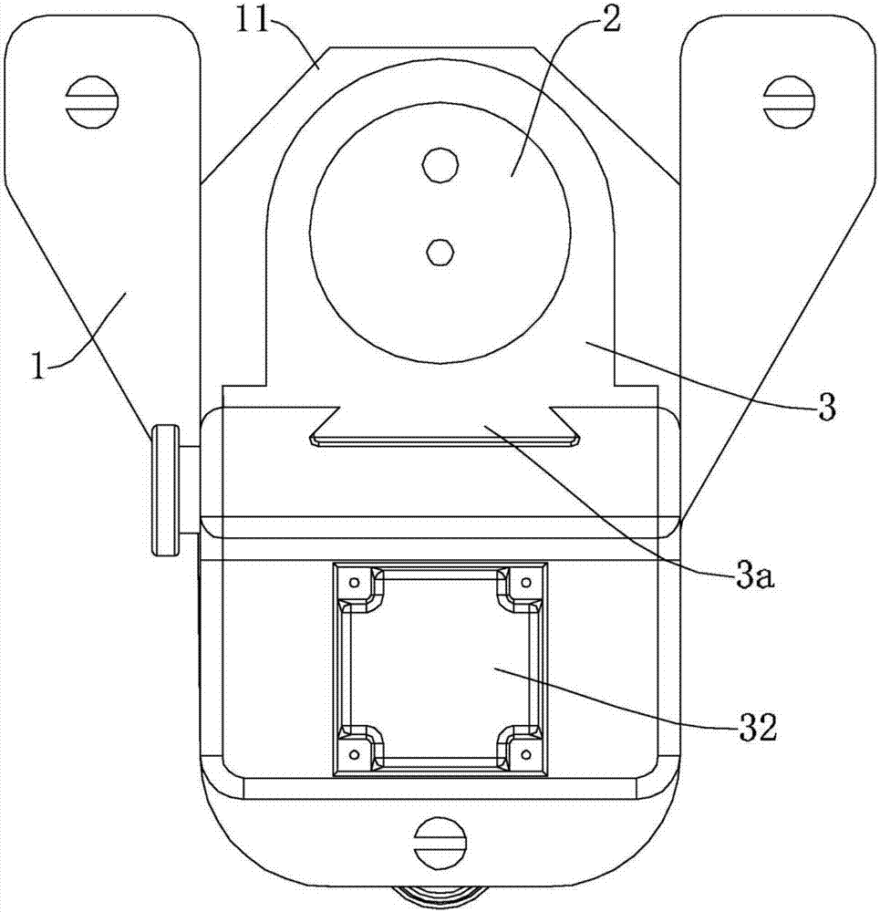
[0032] Figure 1 to Figure 3 Shown is the structural representation of the present invention.

[0033] The reference signs therein are: flat drill floor 1, installation base 11, positioning boss 11a, adjusting support foot 12, ultrasonic electric spindle 2, ultrasonic electric spindle drive module 21, ultrasonic drive drill bit 22, fixed ferrule 3, lifting Guide part 3 a , positioning rack 31 , positioning drive motor 32 , and positioning knob 33 .

[0034] A drilling device for detecting residual stress by the blind hole method of the present invention comprises a flat drill floor 1, the flat drill floor 1 is fixed with an installation base 11, and the installation base 11 is detachably installed with an ultrasonic electric spindle 2 and an ultrasonic The electric spindle drive module 21, the ultrasonic electric spindle 2 is connected with a...


PUM


Abstract

The invention discloses a workpiece residual stress detection method based on ultrasonic driven boring. The method comprises the following steps: 01) polishing workpiece test point surface; 02) pasting a strain rosette to the polished position; 03) connecting the strain rosette and a wiring terminal, and connecting the strain rosette to a corresponding channel of a strain gauge; 04) moving a plane drilling platform onto the surface of a sample, installing a high-precision microscope on the plane drilling platform and carrying out position calibration through the high-precision microscope; 05) dismounting the high-precision microscope and mounting an ultrasonic motorized spindle; 06) after the residual stress value displayed on a computer display screen is stable, adjusting the residual stress value to zero; 07) after turning on a power supply of an ultrasonic motorized spindle driving module, turning on the power supply of a positioning drive module, and controlling drilling feed rate and rotation speed according to a program; and 08) recording and keeping the data after the data is stable. The method can reduce cutting force and can reduce additional stress and additional heat caused by boring itself.

Description

technical field [0001] The invention relates to a method for detecting the residual stress of a workpiece, in particular to a method for detecting the residual stress of a workpiece using ultrasonic-driven drilling. Background technique [0002] During the manufacturing process of the workpiece, it will be affected and affected by various processes and other factors. For example, after welding, casting, cutting machining and other processes, residual stress will often be formed in the workpiece, which will inevitably cause material deformation and reduce the component Ultimate strength and fatigue strength, and even cracks and brittle fractures, etc., which will affect the normal performance of the workpiece. Therefore, how to detect and evaluate the residual stress in the workpiece is particularly important. [0003] The detection methods of residual stress are divided into two types: non-destructive testing and destructive testing, among which destructive testing mainly i...

Claims


Application Information

Patent Timeline
Patent Type & Authority Applications(China)
IPC IPC(8): G01L5/00
CPCG01L5/0047
Inventor 于磊赵夙徐洪涛
Owner NINGBO INST OF MATERIALS TECH & ENG CHINESE ACADEMY OF SCI
Why Eureka
Try Eureka