Circularly-polarized microstrip antenna

A microstrip antenna and circular polarization technology, applied in the field of antennas, can solve the problems of increased loss, complex feeding network structure, and narrow axial ratio bandwidth, etc., and achieve the effects of light weight, high manufacturing precision, and improved axial ratio bandwidth.

Inactive Publication Date: 2017-11-17
成都雷电微力科技股份有限公司
View PDF6 Cites 20 Cited by
  • Summary
  • Abstract
  • Description
  • Claims
  • Application Information

AI Technical Summary

Problems solved by technology

The commonly used single-feed point microstrip antenna achieves circular polarization by cutting the angle on the radiation patch or fine-tuning the aspect ratio of the patch. The disadvantage is that the axial ratio bandwidth is narrow, generally less than 2%
Double-fed or multi-fed

Method used


Image

  • Circularly-polarized microstrip antenna
  • Circularly-polarized microstrip antenna
  • Circularly-polarized microstrip antenna

Examples


Embodiment Construction

[0029] In the following, the present invention will be further described in detail in conjunction with the accompanying drawings and embodiments, so as to make the purpose, technical solutions and advantages of the present invention more clear. It should be understood that the specific embodiments described here are only used to explain the present invention, not to limit the present invention.

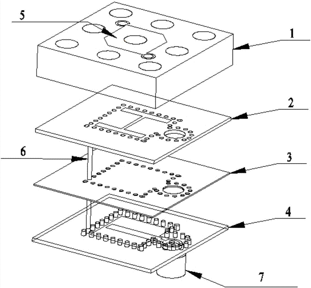
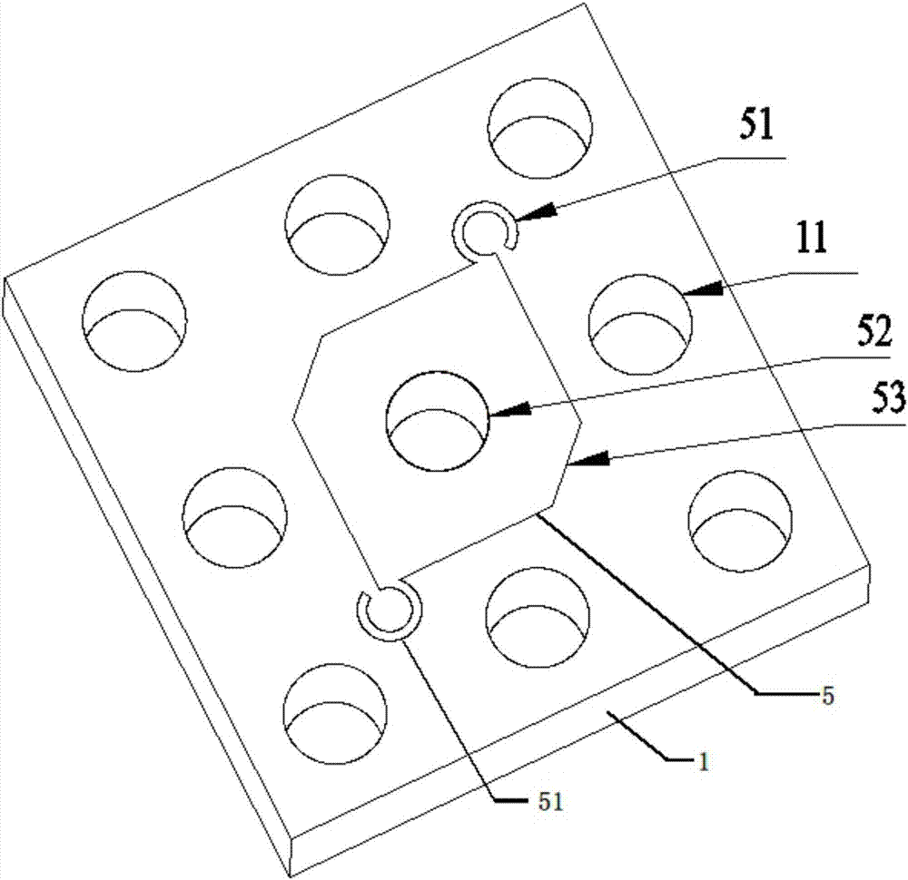
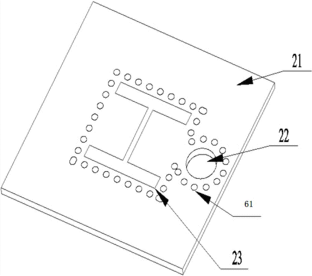
[0030] figure 1 The overall structure of the circularly polarized microstrip antenna according to an embodiment of the present invention is shown. The circularly polarized microstrip antenna includes an upper dielectric substrate 1, an intermediate dielectric substrate 2, a prepreg 3, a lower dielectric substrate 4, a radiation patch 5, a metal through-hole column 6, and a connection structure 7; wherein the radiation patch 5 is located on the upper surface of the upper dielectric substrate 1 to achieve circular polarization performance; the prepreg 3 is located between the intermedi...


PUM

PropertyMeasurementUnit
Radiusaaaaaaaaaa
Radiusaaaaaaaaaa
Radian angleaaaaaaaaaa

Abstract

The invention discloses a circularly-polarized microstrip antenna. The circularly-polarized microstrip antenna comprises an upper dielectric substrate, a middle dielectric substrate, a prepreg, a lower dielectric substrate, a radiation patch, a metal through hole column and a connecting structure, wherein the radiation patch is positioned on the upper surface of the upper dielectric substrate, and is used for realizing circular polarization performance; the prepreg is positioned between the middle dielectric substrate and the lower dielectric substrate, and is used for adhering the middle dielectric substrate and the lower dielectric substrate; the metal through hole column penetrates through corresponding through holes in the middle dielectric substrate, the prepreg and the lower dielectric substrate so as to form a substrate integrated waveguide SIW cavity; a first coupling gap is formed in the middle dielectric substrate; the lower dielectric substrate is provided with a second coupling gap and a strip-shaped feeder line; and the connecting structure is used for leading out the feeder line so as to be connected with an external system. According to the antenna, the circular polarization axial ratio bandwidth and gain are obviously improved, the manufacturing precision is high, and the processing and device cost is low.

Description

technical field [0001] The invention relates to the technical field of antennas, in particular to a circularly polarized microstrip antenna. Background technique [0002] Compared with linearly polarized antennas, circularly polarized antennas have many advantages, such as being very effective in suppressing multipath interference and attenuation, and being able to reduce the Faraday glare effect caused by the ionosphere. In addition, circularly polarized antennas do not require strict directivity between the transmitting and receiving antennas, while linearly polarized antennas will cause polarization mismatch loss if any polarization misalignment occurs between the transmitting and receiving antennas. [0003] Microstrip antennas are widely used in satellite communications, mobile communications, global satellite navigation, wireless sensors, RFID, etc. Radio frequency identification, wireless energy transmission and other systems. There are many schemes for microstrip a...

Claims


Application Information

Patent Timeline
IPC IPC(8): H01Q1/50H01Q1/38H01Q15/24
CPCH01Q1/38H01Q1/50H01Q15/24
Inventor 刘昊肖润均丁卓富张成
Owner 成都雷电微力科技股份有限公司
Why Eureka
Try Eureka