Air pressure type water pumping method and water suction pump
A pneumatic and suction pump technology, applied in the direction of pressure pumps, non-volume pumps, pumps, etc., can solve the problems of complex structure, heavy weight, high operation and maintenance costs, and achieve weight reduction, simple and reasonable structure, and easy operation and maintenance. convenient effect
- Summary
- Abstract
- Description
- Claims
- Application Information
AI Technical Summary
Problems solved by technology
Method used
Image

Examples
Embodiment 1
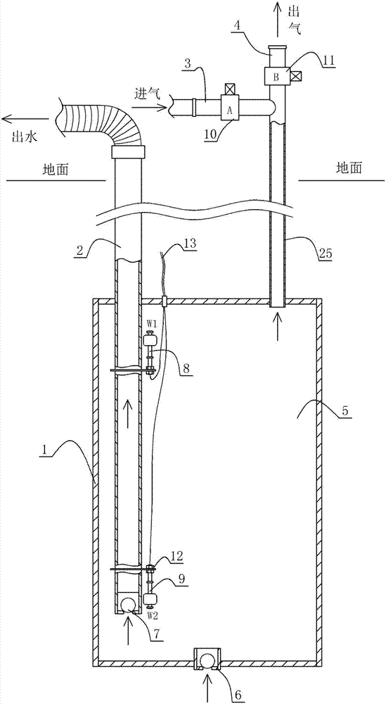
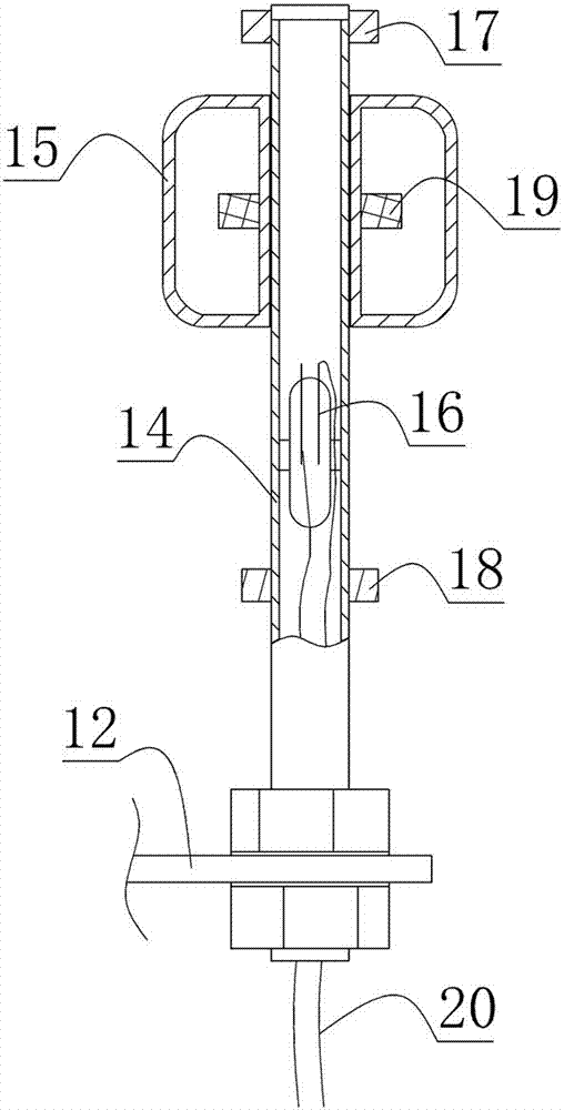
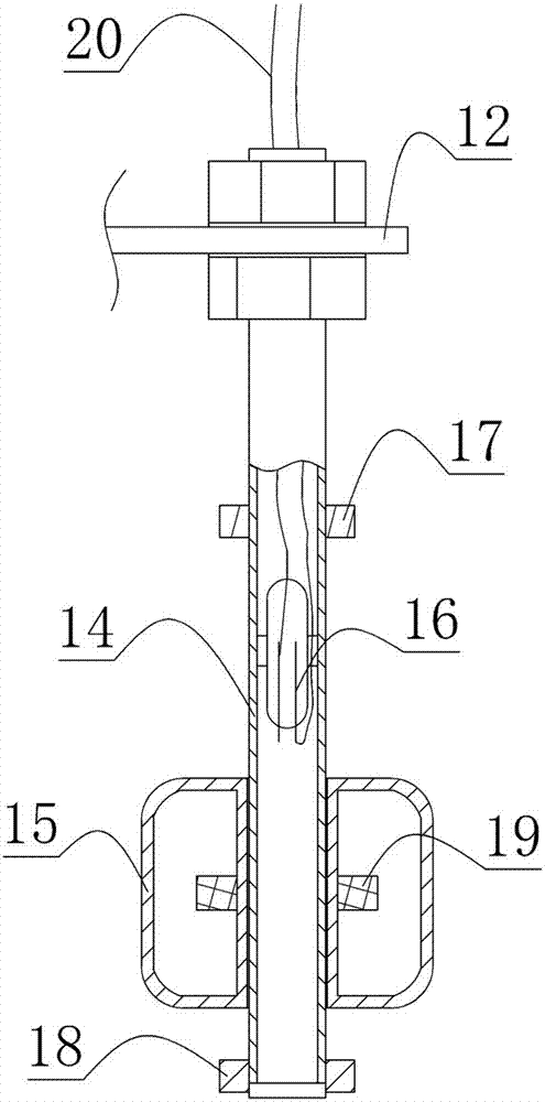
[0029] Example 1, such as figure 1 As shown, the structure diagram of the pneumatic water pump of the first embodiment of the present invention is provided, which consists of a pump body 1, a water outlet pipe 2, an air inlet pipe 3, an air outlet pipe 4, a water inlet check valve 6, and a water outlet valve. Composed of directional valve 7, liquid level gauge, electric control valve A (10) and electric control valve B (11), the inside of the pump body 1 is the inner cavity 5, and the pump body 1 can be in the shape of a cylinder. When in use, the pump body 1 Stand upright. The lower end of the pump body 1 is provided with a water inlet check valve 6, the water inlet check valve only allows the external liquid (water) to enter the inner cavity 5, and does not allow the liquid in the inner cavity 5 to be discharged through the water inlet check valve 6 . The lower end of the water outlet pipe 2 extends into the bottom of the inner chamber 5, and the upper end of the water out...
Embodiment 2
[0043] Example 2, such as Figure 6 and Figure 7 As shown, the structural schematic diagram and the use state of the pneumatic water pump according to the second embodiment of the present invention are provided respectively, except that the connection form between the air inlet pipe 3 and the air outlet pipe 4 and the internal cavity of the pump body 1 is different, All the other structures and working conditions are the same as those in Embodiment 1.
[0044] In this embodiment, both the air inlet pipe 3 and the air outlet pipe 4 communicate directly with the inner chamber 5 of the pump body 1, and the electric control valve A (10) and the electric control valve B (11) are arranged near the pump body. The advantage is that when the electric control valve A is opened, the pressure gas can enter the inner chamber 5 of the pump body 1 through the inlet pipe 3 instantly; when the electric control valve B is opened, the gas in the pump body 1 can quickly flow from the outlet pip...
Embodiment 3
[0045] Example 3, such as Figure 8 and Figure 9 As shown, the structural schematic diagram and the use state of the pneumatic water pump of the third embodiment of the present invention are respectively provided. Compared with Embodiment 1, it does not use a circuit, and saves the electric control valves A, B and The upper and lower end liquid level gauges, but a two-position three-way valve 26, a floating ball 28 and a counterweight 29 are added. The common port of the two-position three-way valve 26 communicates with the inner chamber 5 of the pump body 1, and the intake pipe 3 communicates with the inner cavity 5 of the pump body 1. The first selection port of the two-position three-way valve 26 communicates, and the outlet pipe 4 communicates with the second selection port of the two-position three-way valve 26 . The two-position three-way valve 26 is provided with a connecting rod 27. When the connecting rod 27 is at the upper end position, the second selection port ca...
PUM
 Abstract
Description
Claims
Application Information
 - R&D
- Intellectual Property
- Life Sciences
- Materials
- Tech Scout
- Unparalleled Data Quality
- Higher Quality Content
- 60% Fewer Hallucinations
Browse by: Latest US Patents, China's latest patents, Technical Efficacy Thesaurus, Application Domain, Technology Topic, Popular Technical Reports.
© 2025 PatSnap. All rights reserved.Legal|Privacy policy|Modern Slavery Act Transparency Statement|Sitemap|About US| Contact US: help@patsnap.com