Tube internal and external expansion type spiral corrugated tube

A technology of corrugated tubes and helical waves, which is applied in the field of helical corrugated tubes with internal and external expansion, can solve the problems of insignificant improvement of comprehensive heat transfer performance and increased resistance, and achieve the purpose of inhibiting tube wall scaling, reducing resistance, and reducing The effect of flow resistance

Inactive Publication Date: 2017-11-21
HARBIN INST OF TECH
View PDF7 Cites 4 Cited by
  • Summary
  • Abstract
  • Description
  • Claims
  • Application Information

AI Technical Summary

Problems solved by technology

[0005] In order to solve the problem that the existing enhanced heat exchange tube structure causes a large increase in the local flow resistance inside and outside the tube, and

Method used


Image

  • Tube internal and external expansion type spiral corrugated tube

Examples


specific Embodiment approach 1

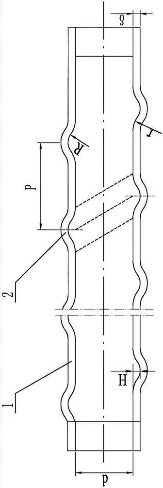
[0014] Specific implementation mode one: combine figure 1 Describe this embodiment mode. The internally and externally expanding helical corrugated tube described in this embodiment comprises a hollow tube body 1. A helical corrugated node channel 2 is provided on the outer peripheral side wall of the hollow tube body 1. The helical corrugated node channel 2 are uniformly arranged in a helical shape along the length direction on the outer peripheral side wall of the hollow pipe body 1, and the cross section of the helical node channel 2 is an arc shape with the middle protruding outward along the radial direction.

[0015] The helical nodal channel 2 is designed in this way to be a channel with a convex structure that spirals inside and outside the hollow tube body 1. The helical nodal channel 2 is formed in the hollow tube body 1 by liquid expansion, and is used to seal the hollow tube body when the fluid passes through. 1 to form a swirl.

[0016] The fluid forms vortices w...

specific Embodiment approach 2

[0017] Specific implementation mode two: combination figure 1 This embodiment will be described. The helical nodal channel 2 in this embodiment is arranged in a counterclockwise direction on the outer peripheral side wall of the hollow tubular body 1 . Other compositions and connection methods are the same as those in Embodiment 1.

[0018] The fluid in the hollow tube body 1 flows through the helical structure in such a design, which can increase the fluid disturbance and increase the heat exchange effect. At the same time, the helical structure has the effect of rectification, allowing the fluid to obtain the normal phase velocity, forming a swirling flow, reducing flow resistance, and increasing the heat exchange time. To sum up, the spiral structure can improve the comprehensive heat transfer performance of the heat exchange tube.

specific Embodiment approach 3

[0019] Specific implementation mode three: combination figure 1 This embodiment will be described. The height H of the helical nodal channel 2 in this embodiment is 2.5 mm. Other compositions and connection modes are the same as those in Embodiment 1 or 2.


PUM

PropertyMeasurementUnit
Heightaaaaaaaaaa
Arc radiusaaaaaaaaaa
The inside diameter ofaaaaaaaaaa

Abstract

The invention discloses a tube internal and external expansion type spiral corrugated tube, and relates to the field of heat transfer devices. The invention aims to solve the problem that local resistance of the internal and external flowing of the tube is large and the comprehensive heat exchange performance improvement is not obvious due to the structure of an existing reinforced heat exchange tube. The tube internal and external expansion type spiral corrugated tube comprise a hollow pipe body, a spiral corrugated channel is arranged on the outer circumference side wall of the hollow pipe body, the spiral corrugated channel is spirally and uniformly arranged on the outer circumference side wall of the hollow pipe body in the length direction, the cross section of the spiral corrugated channel is an arc shape with the middle part protruding outwards in the radial direction. The tube internal and external expansion type spiral corrugated tube is used for reinforcing heat exchange technology.

Description

technical field [0001] The invention relates to the field of heat transfer devices, in particular to a spiral corrugated tube with internal and external expansion. Background technique [0002] Enhanced heat transfer technology is widely used in petroleum, chemical industry, electric power, metallurgy, shipbuilding, machinery, heating, food and refrigeration and other fields, and the typical equipment used includes heat exchangers, air conditioners, chemical reaction equipment and refrigeration equipment. The gas-gas (steam) heat exchanger is an important equipment to realize the recovery of high-temperature waste gas waste heat in the industrial sector. The application of its enhanced heat transfer technology makes the traditional gas-gas (steam) heat exchanger gradually develop into a high-efficiency and compact type, and A rich variety of structure types is derived. Among the three types of enhanced heat transfer technologies, passive enhanced heat transfer can effective...

Claims


Application Information

Patent Timeline
IPC IPC(8): F28F1/08
CPCF28F1/08
Inventor 李炳熙陈鑫张亚宁王维
Owner HARBIN INST OF TECH
Why Eureka
Try Eureka