
Micro-mechanical harmonic oscillator with adjustable gap between electrode and vibrating disk

A micro-mechanical resonator and electrode technology, applied in the direction of electrical components, impedance networks, etc., can solve the problems of high resonator production cost, high dynamic resistance, high manufacturing process requirements, etc., to improve the Q value and resonator performance, processing technology The effect of low difficulty

Inactive Publication Date: 2013-01-02
UNIV OF ELECTRONIC SCI & TECH OF CHINA
View PDF3 Cites 2 Cited by
  • Summary
  • Abstract
  • Description
  • Claims
  • Application Information

AI Technical Summary

Problems solved by technology

Since then, Cornell University has also used the same instrument to deposit hafnium dioxide on the inner side of the electrode, and obtained a 10nm gap; however, the equipment of the atomic layer deposition system is expensive and the cost of resonator production is high.
In the patent document with the publication number CN102280682A and the name "A Micromechanical Disc Resonator", a vibrating disc including a substrate and a DC bias wire provided on the substrate is disclosed. Two ring-type AC input electrodes and AC output electrodes, a pair of fixed strips for positioning the input electrodes and output electrodes, and a pair of suspended corrugated beam micromechanical disc resonators; The fixed input and output electrodes fixed on the resonator substrate in the traditional micromechanical disk resonator are changed to suspension type, and the electrodes are pulled to the vibrating disk by using DC bias voltage, and then the input and output electrodes are fixed by positioning strips ; However, although this technology can improve the energy conversion efficiency of the resonator and reduce the production cost to a certain extent, it requires that the initial seam (gap) between the positioning bar and the electrode should be ≤ the vibration disc and the The initial slit (gap) gap between the electrodes, and the gap width mentioned in the patent is already the narrowest width (100nm) that can be achieved by a common process. If the initial gap between the positioning bar and the electrode is larger than the initial gap between the vibrating disc and the electrode due to the precision of the process (lithography, etching, etc.), it will cause the input and output electrodes and the positioning The strips are not in contact, but the input and output electrodes are in contact with the vibrating disk and short-circuited, causing the resonator to fail; and this technology requires that the inner radian of the input and output electrodes must be greater than the radian of the disc, which will also increase the dynamic resistance of the resonator
Therefore, this technology still has high manufacturing process requirements, and it is difficult to further reduce the width of the gap between the input and output electrodes and the vibrating disc under the existing conventional process conditions, as well as the dynamic resistance caused by the inconsistency between the radians of the input and output electrodes and the radians of the vibrating disc. High, which limits the further improvement of the overall performance of the resonator and other disadvantages

Method used


Image

  • Micro-mechanical harmonic oscillator with adjustable gap between electrode and vibrating disk
  • Micro-mechanical harmonic oscillator with adjustable gap between electrode and vibrating disk
  • Micro-mechanical harmonic oscillator with adjustable gap between electrode and vibrating disk

Examples


Embodiment 1

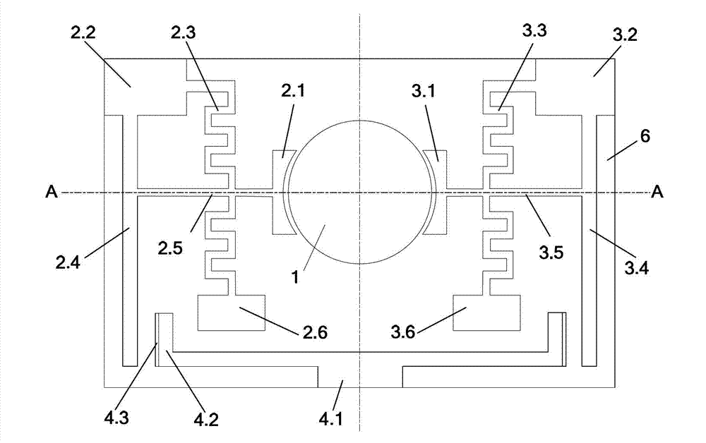
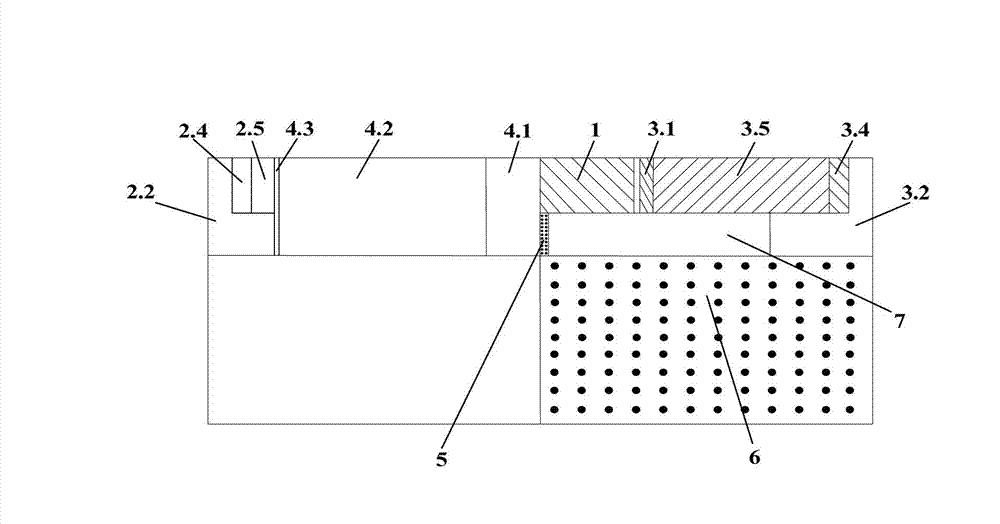
[0013] Embodiment 1: The material of the substrate 6 is silicon (length×width×thickness=25 μm×18 μm×5 μm); the vibrating disk 1 is made of polysilicon, the radius R is 1.9 μm, the thickness is 1 μm, and the bottom surface of the disk body and the substrate are The distance is 0.8 μm; the input and output electrodes 2.1 and 3.1 are doped polysilicon, the distance between each electrode and the substrate is also 0.8 μm, and the thickness is 1 μm. The curvature radius R of the arc inside the electrode is 2 μm, and the arc is л / 2 ; AC input and output connectors 2.2 and 3.2 are also doped with polysilicon, (length × width × height = 4 μm × 3 μm × 1.8 μm); input and output electrode arms 2.4 and 3.4 are made of polysilicon, (length × width × height = 12 μm × 1 μm×1 μm); the input and output electrode rods 2.5 and 3.5 are made of doped polysilicon, the width is 0.5 μm, the distance from the substrate is 0.8 μm, and the thickness is 1 μm; and the elastic guide arms 2.3 and 3.3 are ado...

Embodiment 2

[0018] Embodiment 2: In this embodiment, the initial gap between the input and output electrodes 2.1, 3.1 and the vibrating disk 1 is still 100nm, and the connecting part of the electrode arm and the electrode rod is half the distance from the fixed end of the electrode arm. The initial distance between the electrode arms 2.4, 3.4 and the insulating sheet 4.3 is 220nm, and the rest are the same as in Example 1; the gap between the vibrating disk 1 and the input and output electrodes 2.1, 3.1 in the working (charged) state is also 10nm.


PUM


Abstract

The invention provides a micro-mechanical harmonic oscillator with an adjustable gap between an electrode and a vibrating disk, and belongs to the technical field of RF communication and micro-electromechanical systems (MEMS). The oscillator comprises a substrate, a vibrating disk arranged on the substrate, an annular-piece AC input electrode, an annular-piece AC output electrode and joints on both sides of the vibrating disk, a static electrode with a positioning head, insulating pieces on both end surfaces, and an input and output electrode movable positioning assembly comprising an electrode rod, an electrode arm and an elastic guiding arm. According to the invention, because the static electrode with a positioning head and the input and output electrode movable positioning assembly are additionally arranged on the substrate, the gap (Electrified Gap) among the input and output electrodes and the vibrating disk in working can be controlled at about 10nm and a wedge-shape intermittence cannot be formed, so that the micro-mechanical harmonic oscillator with an adjustable gap between an electrode and a vibrating disk has the characteristics that the gap between the input and output electrodes and the vibrating disk in working and the dynamic resistance of the disk harmonic oscillator in working can be effectively reduced, the Q value of the harmonic oscillator is high, the performance of the harmonic oscillator is outstanding.

Description

technical field [0001] The invention belongs to the technical field of components in the technical fields of radio frequency communication and micro-electromechanical systems (MEMS), and in particular relates to a MEMS resonator whose gap between input and output electrodes and a vibrating disc can be dynamically adjusted. Background technique [0002] Micromechanical Disk Resonator (MEMS disk resonator for short) is a kind of radio frequency resonator that is developing rapidly in recent years, and can be widely used in radio frequency circuits such as oscillators and filters. MEMS disk resonators have advantages such as small size, high Q (ratio of energy storage to energy consumption), low power consumption, and easy integration, which make them have great advantages and prospects compared with traditional resonators. In a disk resonator, the distance between the input and output electrodes and the vibrating disk and the overlapping area directly determine the dynamic res...

Claims


Application Information

Patent Timeline
IPC IPC(8): H03H9/24H03H3/02
Inventor 鲍景富何宗郭蒋俊文杜亦佳
Owner UNIV OF ELECTRONIC SCI & TECH OF CHINA
Learn More