Method of monitoring effective chemical shrinkage rate of thermoset composite in real time

A composite material and chemical shrinkage technology, applied in the direction of material thermal expansion coefficient, measuring device, optical device, etc., to optimize the curing process and reduce the effect of chemical shrinkage

Inactive Publication Date: 2017-11-21
WUHAN UNIV OF TECH
View PDF8 Cites 8 Cited by
  • Summary
  • Abstract
  • Description
  • Claims
  • Application Information

AI Technical Summary

Problems solved by technology

Traditional testing methods are mainly aimed at measuring the shrinkage rate of the material throughout the curing process, and even the test object is the total volume change before and after curing rather than the effective chemical shrinkage rate

Method used


Image

  • Method of monitoring effective chemical shrinkage rate of thermoset composite in real time
  • Method of monitoring effective chemical shrinkage rate of thermoset composite in real time
  • Method of monitoring effective chemical shrinkage rate of thermoset composite in real time

Examples


Embodiment 1

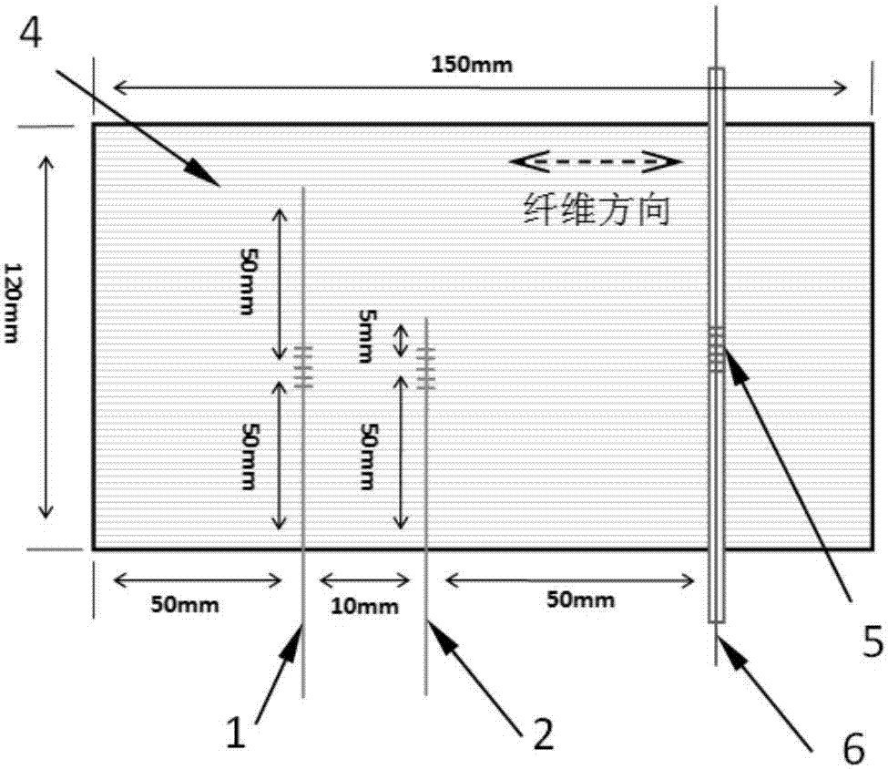
[0035] The method of the invention is used for monitoring the transverse effective chemical shrinkage rate of the carbon fiber / epoxy prepreg in the autoclave curing process.

[0036] In this example, tail-cut FBG groups with different lengths of pigtails were used to embed them in carbon fiber / epoxy unidirectional prepreg tape, and the gel point and transverse effective chemical shrinkage rate during the autoclave molding process were successfully monitored.

[0037] 1. Tail-cut FBG groups were prepared according to the following steps:

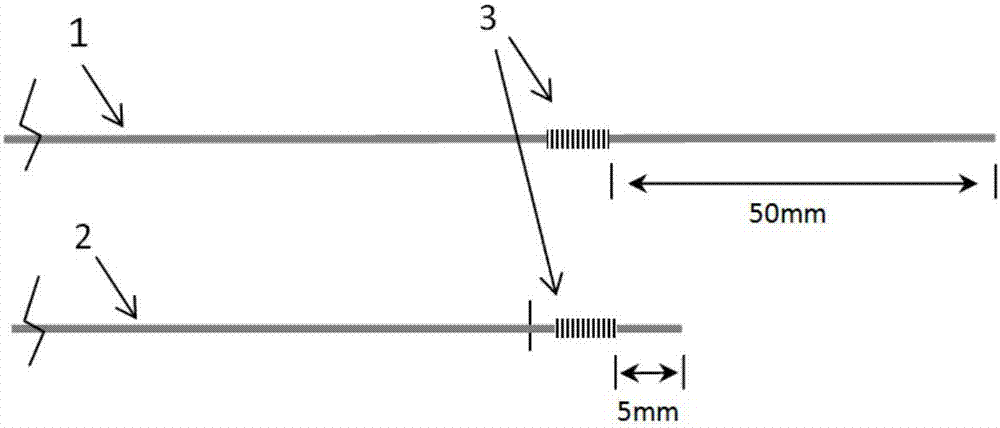
[0038] 1) if figure 1 As shown, select two FBG sensors whose length is 5mm and the center wavelength is 1550nm, and use wire strippers to strip the coating layer within 50mm on both sides of the sensing band.

[0039] 2) Select one of them and cut it at a distance of 5mm from one side of the sensing section to obtain the short-tailed FBG sensor 2, denoted as FBG-S.

[0040] 3) Select another one and cut it off at a distance of 50 mm from on...

Embodiment 2

[0055] The method of the invention is used for monitoring the transverse effective chemical shrinkage rate of the composite material during the vacuum introduction process.

[0056] In this example, tail-cut FBG groups with different lengths of pigtails were used to embed them in glass fiber / epoxy composite materials, and the gel point and transverse effective chemical shrinkage rate during the vacuum introduction process were successfully monitored.

[0057] 1. Tail-cut FBG groups were prepared according to the following steps:

[0058] 1) Select two FBG sensors with a length of 3mm and a center wavelength of 1545nm, and use wire strippers to peel off the coating layer within 50mm on both sides of the sensing band.

[0059] 2) Select one of them and cut it at a distance of 5mm from one side of the sensing section to obtain the short-tailed FBG sensor FBG-S.

[0060] 3) Select another one and cut it at a distance of 60 mm from one side of the sensing section to obtain the lon...


PUM

PropertyMeasurementUnit
lengthaaaaaaaaaa
wavelengthaaaaaaaaaa
lengthaaaaaaaaaa

Abstract

The invention provides a method of monitoring an effective chemical shrinkage rate of a thermoset composite in real time. The method comprises the following steps of: 1) selecting a truncated FBG (fiber bragg grating) group and a temperature reference grating, burying the truncated FBG group and the temperature reference grating in a unidirectional laminate of the thermoset composite, 3) performing curing molding, recording central wavelength variations of the truncated FBG group and the temperature reference grating in a curing process at the same time, 4) subtracting a central wavelength variation value of the temperature reference grating from central wavelength variation values of a long-tail FBG sensor and a short-tail FBG sensor, then dividing by a strain sensitivity coefficient to form strain variations of the long-tail FBG sensor and the short-tail FBG sensor, and 5) selecting a gel point and a glass transition point, and taking a strain variation value monitored by the long-tail FBG sensor between the gel point and the glass transition point at constant temperature stage in the curing process as the transverse effective chemical shrinkage rate of the composite, wherein the truncated FBG group comprises the long-tail FBG sensor and the short-tail FBG sensor. The method is simple, practicable and high in testing accuracy.

Description

technical field [0001] The invention belongs to the field of material testing research, and in particular relates to a method for real-time monitoring of the effective chemical shrinkage rate of thermosetting composite materials, which is used for testing the effective chemical shrinkage rate of thermosetting composite materials in the curing process. Background technique [0002] As a new type of lightweight and high-strength material, thermosetting composites have been widely used in the fields of aerospace, rail transit and ships. The curing process of thermosetting composite materials is essentially a process in which the thermosetting resin produces a chemical crosslinking reaction under the action of temperature, its molecular structure is transformed from a linear small molecule to a body-shaped network structure, and the fiber material is fixed. During this process, the intermolecular force of the thermosetting resin is converted from van der Waals force to chemical ...

Claims


Application Information

Patent Timeline
Patent Type & Authority Applications(China)
IPC IPC(8): G01N25/16G01B11/16
CPCG01N25/16G01B11/165
Inventor 李书欣胡海晓曹东风刘立胜王继辉
Owner WUHAN UNIV OF TECH
Why Eureka
Try Eureka