
Steel-structure-free overhead photovoltaic assembly support system and power transmission system

A photovoltaic module and support system technology, applied in photovoltaic power generation, photovoltaic modules, solar heating systems, etc., can solve the problems of high manual installation costs, long construction period, manpower, material and financial resources, and achieve a sharp drop in construction and installation costs , The effect of improving land utilization and shortening the construction period

Pending Publication Date: 2017-11-21
付佳临
View PDF9 Cites 1 Cited by
  • Summary
  • Abstract
  • Description
  • Claims
  • Application Information

AI Technical Summary

Problems solved by technology

[0003] (1) The existing photovoltaic support of the same specification occupies a large area, and the site is required to be flat, with an average area of ​​about 35-40 mu per 1MW, which occupies a huge amount of resources for the increasingly tense land resources;
[0004] (2) The amount of civil construction is large, and the existing installation method is used. In the implementation, only the production of the cement foundation base consumes a lot of manpower, material and financial resources. Specifically, every 1MW needs to lay the foundation on average The maximum number of piles is about 1000-1200;
[0006] (4) The cost of manual installation is huge. Usually, 1MW requires at least 50 manual installations. The production, processing and installation period is about 3 months, and the installation period is 3 months.
[0007] (5) The original support structure has a single function, and the support body is only used to support the photovoltaic modules by using fixed brackets or steel structures and truss structures, and cannot realize current transmission while supporting. While supporting the photovoltaic modules, it also uses the load-bearing cables to transmit the electric energy generated by the photovoltaic modules
[0009] In order to achieve this goal, the existing methods cannot be realized at all. At present, all the main support structures of solar photovoltaic power generation are processed and installed with fixed brackets, steel structures or truss structures. The steel consumption of tiles has exceeded 160 tons; the construction process is complicated, and at the same time, thousands of cubic meters of civil works need to be excavated, nearly a thousand columns of foundations should be built, the construction period is long, and the investment cost is huge.

Method used


Image

  • Steel-structure-free overhead photovoltaic assembly support system and power transmission system
  • Steel-structure-free overhead photovoltaic assembly support system and power transmission system
  • Steel-structure-free overhead photovoltaic assembly support system and power transmission system

Examples


Embodiment 1

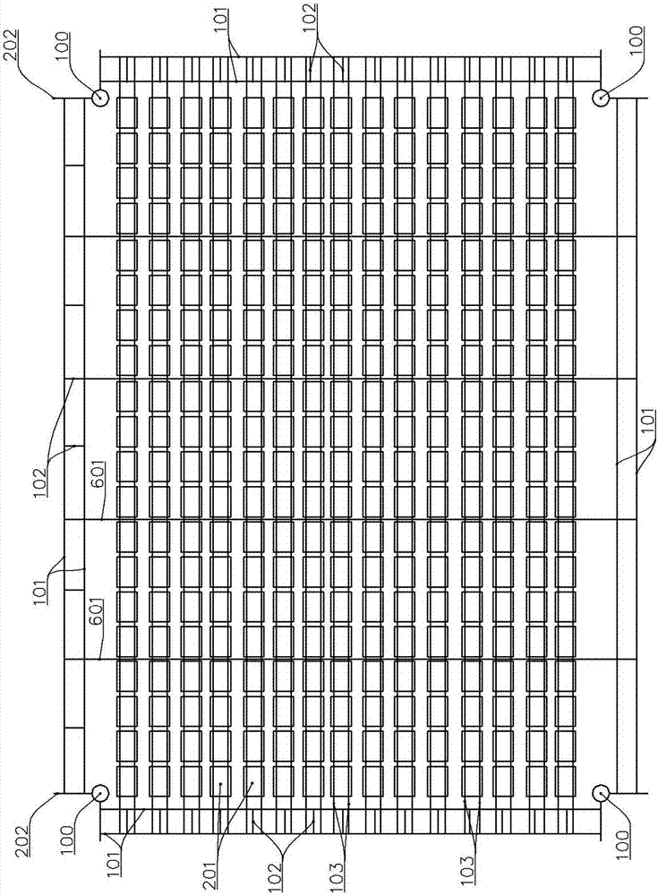
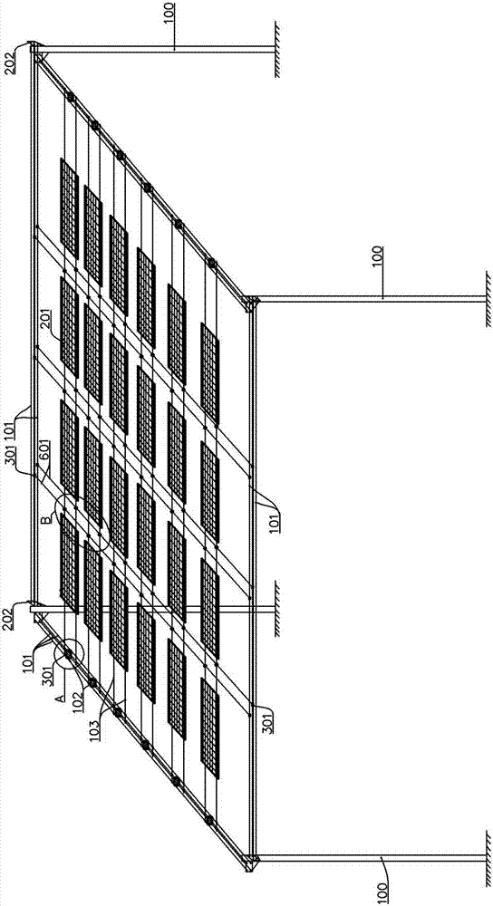
[0064] Example 1: A support system for overhead photovoltaic modules without a steel structure, see Figure 1 to Figure 27 .

[0065] For ease of understanding and description, this embodiment 1 first uses the more commonly used and easy-to-understand conventional layout method as an example for illustration. First, see Figure 1 to Figure 4 , the system includes four columns 100 distributed at the four corners, the main cables 101 are connected between two adjacent columns, the main cables 101 are in the shape of a "mouth" or a rectangle, the main cables of the two adjacent columns Lasso as a group.

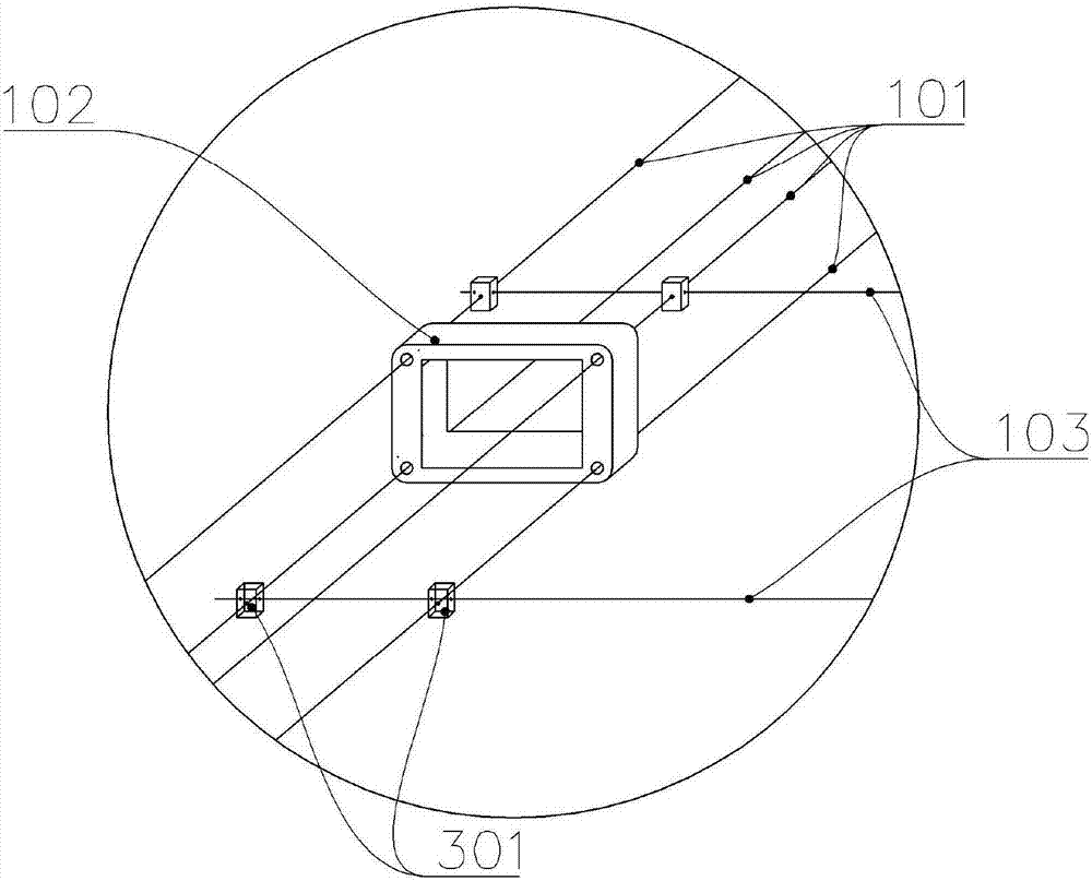
[0066] like figure 2 , 3 , 12, and 17, the main drag cables 101 in the same group are four and arranged in a rectangular arrangement, and the four main drag cables 101 are connected by clamps 102 to form a rigid whole, as Figures 10 to 14 As shown, the jig can be in the shape of a straight plate or rod, or in the shape of a triangle, a quadrangle, or a multi-deformation or...

Embodiment 2

[0080] Embodiment 2, the similarities with Embodiment 1 will not be repeated, the difference is; except the above-mentioned conventional design, the upright column in this design is not limited to above-mentioned four, can be at least two, and can adopt any way layout, see Figure 5 to Figure 7 , in the same way, main cables 101 can be arranged between any two uprights in this state, and the two ends of the load-bearing cables 103 intersecting each other or arranged parallel to each other can be connected with any two main cables.

[0081] Similarly, the main cables between the above-mentioned two uprights can also be multiple, such as Figures 10 to 14 As shown, the main cables can also be connected by clamps to form a rigid whole. Several clamps are used to make rigid redundant fixed connections of the above-mentioned main cables in a direction parallel to the cross-section of the main cables according to a certain ratio interval, and finally form a frame. polygonal structu...

Embodiment 3

[0082] Embodiment 3. This embodiment designs a steel-free overhead photovoltaic module power transmission system. This power transmission system uses the steel-free overhead photovoltaic module support system as described in Embodiment 1. The load-bearing cables described in the system As a metal wire, the photovoltaic module is electrically connected to the load-bearing cable, and the electric energy generated by the photovoltaic module is transmitted through the load-bearing cable.


PUM


Abstract

The invention provides a steel-structure-free overhead photovoltaic assembly support system and power transmission system which are high in space utilization rate, less in steel consumption, convenient to install, less in human and material resource input and easy to construct. The steel-structure-free overhead photovoltaic assembly support system comprises at least three vertical columns distributed at different positions, and a main inhaul cable is arranged between any two vertical columns; and the steel-structure-free overhead photovoltaic assembly support system further comprises a load-bearing cable, wherein two ends of the load-bearing cable are connected with any two main inhaul cables respectively, and a photovoltaic assembly is arranged on the load-bearing cable. The steel-structure-free overhead photovoltaic assembly power transmission system applies the steel-structure-free overhead photovoltaic assembly support system. The load-bearing cable also acts as a metal wire in addition to bearing the load. The photovoltaic assembly and the load-bearing cable form electrical connection. Electric energy generated by the photovoltaic assembly is transmitted through the load-bearing cable.

Description

technical field [0001] The invention relates to the technical field of photovoltaic power generation and power transmission and distribution, in particular to a steel-free overhead photovoltaic module support system and power transmission system, which is characterized in that combined steel cables are connected to each other through clamps or positioning lockers, Make its load-bearing capacity meet the requirements of use, and achieve the role of completely replacing the fixed brackets, steel structures, and truss structures in the existing support methods. While the system plays a supporting role, its load-bearing cables also shoulder the responsibility of current transmission. This system can It is suitable for situations where the span is large and the surrounding environment is complex and the ground space is limited. Background technique [0002] At present, in the field of photovoltaic power generation, whether it is in a centralized power station or a distributed pow...

Claims


Application Information

Patent Timeline
Patent Type & Authority Applications(China)
IPC IPC(8): H02S20/00H02S20/10H02S20/22F24J2/52
CPCH02S20/00H02S20/10H02S20/22F24S25/50Y02B10/10Y02E10/50Y02E10/47
Inventor 付佳临
Owner 付佳临
Learn More