Automatic error correction electrocardiogram system and method
An automatic error correction, electrocardiogram technology, applied in medical science, sensors, diagnostic recording/measurement, etc., can solve the problems of unsuitable electrocardiogram examination, unsuitability, etc., to ensure accuracy, reduce workload, and accurately receive and convert signals. Effect
- Summary
- Abstract
- Description
- Claims
- Application Information
AI Technical Summary
Problems solved by technology
Method used
Image
Examples
Embodiment 1
[0052] See Figure 4 , Figure 4 It is a schematic diagram of the automatic error correction electrocardiogram system of embodiment 1 of the present invention. The automatic error correction electrocardiogram system includes an electrode lead assembly 1, a signal processing module 2, a position information acquisition device 3, a position information processing module 4, and a display module 5.
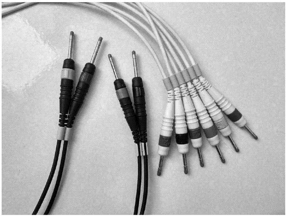
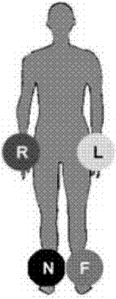
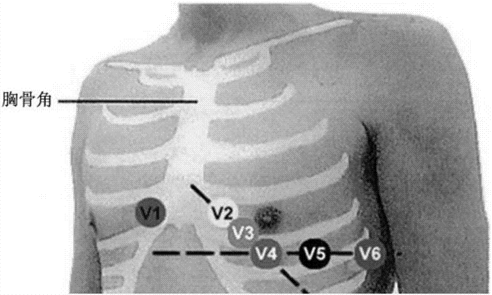
[0053] See Figure 5 , Figure 5 It is a schematic diagram of the electrode lead assembly of Example 1 of the present invention. The electrode lead assembly 1 includes ten electrode leads, specifically four limb electrode leads and six chest electrode leads (V1, V2, V3, V4, V5, V6). Each electrode lead includes an electrode 11 and a lead wire 12 connected to it. The electrode 11 is used to obtain the bioelectric phenomenon of the human body, especially the potential of the test point of the human skin, and the lead wire 12 is used to transmit the electrocardiographic signal collected by...
Embodiment 2
[0060] The automatic error correction electrocardiogram system of this embodiment is the same as that of Embodiment 1, except that the position identification of the electrode lead assembly 1 is different from that of Embodiment 1. Specifically, see Figure 7 , Figure 7 It is a schematic diagram of the electrode lead assembly of Example 2 of the present invention. The electrode lead assembly 1 includes ten electrode leads, specifically four limb electrode leads and six chest electrode leads (V1, V2, V3, V4, V5, V6). Each electrode lead includes an electrode 11 and a lead wire 12 connected to it. The lead wire 12 is provided with an identification body 111 that surrounds the lead wire 12 and is connected to the lead wire 12 Line 12 ribbons of different colors. The identification body 111 on the limb electrode lead is specifically the first identification body 1111, which is white and 1 cm wide. The four limb electrode leads respectively have one, two, three, and four first i...
Embodiment 3
[0063] The automatic error correction electrocardiogram system of this embodiment is the same as that of embodiment 1, except that: the electrode 11 is equipped with a radio signal generator, and the radio signal generator on different electrodes 11 emits radio signals of different bands. The position information collecting device 3 is specifically a radio signal receiver, which is used to receive a signal from a radio signal generator and transmit it to the position information processing module 4 to calculate the position.
[0064] In this embodiment, radio signals of different bands emitted by each radio signal generator constitute the position information of each electrode lead assembly 1. This method is more convenient for the position information processing module 4 to accurately calculate the position, and the overall structure is simpler.
PUM
 Abstract
Description
Claims
Application Information
 - R&D
- Intellectual Property
- Life Sciences
- Materials
- Tech Scout
- Unparalleled Data Quality
- Higher Quality Content
- 60% Fewer Hallucinations
Browse by: Latest US Patents, China's latest patents, Technical Efficacy Thesaurus, Application Domain, Technology Topic, Popular Technical Reports.
© 2025 PatSnap. All rights reserved.Legal|Privacy policy|Modern Slavery Act Transparency Statement|Sitemap|About US| Contact US: help@patsnap.com


