Laser focus control system, application thereof and laser cleaning head

A control system and laser cleaning technology, which is applied in the laser field, can solve problems such as the inability to realize cleaning in narrow spaces, and can not meet the cleaning requirements, so as to improve the quality and efficiency of cleaning, facilitate implementation, and ensure accuracy.

Inactive Publication Date: 2017-11-24
NINGBO INST OF MATERIALS TECH & ENG CHINESE ACADEMY OF SCI +1
View PDF3 Cites 10 Cited by
  • Summary
  • Abstract
  • Description
  • Claims
  • Application Information

AI Technical Summary

Problems solved by technology

However, due to the impact of the rollers, this cleaning head cannot clean in a narrow space, and the cleaning process is contact type, which cannot meet the cleaning of products with special requirements.

Method used


Image

  • Laser focus control system, application thereof and laser cleaning head

Examples


Embodiment 1

[0069] Embodiment 1 laser cleaning

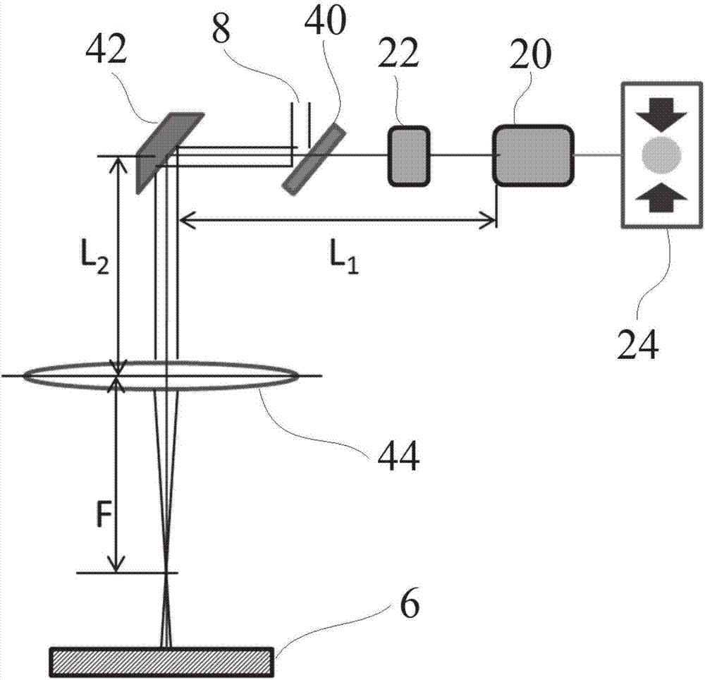
[0070] The laser focus control system in this embodiment is as figure 1 As mentioned in the above, it includes: a laser range finder 20 , a filter 22 , a calculation display unit 24 , a beam splitter 40 , a scanning galvanometer 42 , a field mirror 44 , and a working laser 8 . In this embodiment, the working laser 8 is a cleaning laser.

[0071] Specifically, the ranging laser beam emitted by the laser rangefinder 20 passes through the filter 22, passes through the beam splitter 40 and shoots to the scanning galvanometer 42 on the same optical path as the working laser 8 reflected by the beam splitter 40, and the scanning galvanometer 42 After reflection, it passes through the field lens 44 to irradiate the surface of the workpiece 6 to be processed and measure the distance to obtain the distance measurement result L. In this embodiment, the workpiece 6 to be processed is the workpiece to be cleaned.

[0072] Wherein, the calculation and...

Embodiment 2

[0090] Embodiment 2 laser cleaning

[0091] Use a handheld laser cleaning device to clean the rusty carbon steel material, replace the field lens 44, and reset ΔF according to the focal length F of the new field lens 44 and the material to be cleaned.

[0092] The cleaning head of the handheld laser cleaning device adopts a laser focus control system, and its schematic diagram is as follows figure 1 Shown, its mode of operation is the same as embodiment 1.

Embodiment 3

[0093] Embodiment 3 laser texture

[0094] The laser focus control system in this embodiment is as figure 1 As mentioned in the above, it includes: a laser range finder 20 , a filter 22 , a calculation display unit 24 , a beam splitter 40 , a scanning galvanometer 42 , a field mirror 44 , and a working laser 8 . In this embodiment, the working laser 8 is a processing laser.

[0095] Specifically, the ranging laser beam emitted by the laser rangefinder 20 passes through the filter 22, passes through the beam splitter 40 and shoots to the scanning galvanometer 42 on the same optical path as the working laser 8 reflected by the beam splitter 40, and the scanning galvanometer 42 After reflection, it passes through the field lens 44 to irradiate the surface of the workpiece 6 to be processed and measure the distance to obtain the distance measurement result L. In this embodiment, the workpiece 6 to be processed is the material to be processed.

[0096] Wherein, the calculation a...


PUM


Abstract

The invention discloses a laser focus control system, an application of the laser focus control system and a laser cleaning head. The laser focus control system comprises a laser distance measuring meter, a field lens and a calculation and display unit, wherein a distance measuring laser beam sent by the laser distance measuring meter passes through the field lens, then is irradiated onto the surface of a workpiece and measures distance, the laser distance measuring meter is electrically connected with the calculation and display unit, the laser distance measuring meter and the calculation and display unit input a distance measuring result, and the calculation and display unit outputs at least one signal. The laser focus control system can monitor the defocusing distance in real time, is applicable to the field of laser cleaning, can achieve non-contact laser cleaning, particularly cleaning in narrow spaces, and can improve the cleaning quality and efficiency.

Description

technical field [0001] The application relates to a laser focus control system and its application, the laser focus control system and its application, and a laser cleaning head, belonging to the laser field. Background technique [0002] With the continuous development of science and technology, laser is continuously applied to various fields such as material processing, manufacturing and cleaning. Among them, laser cleaning technology is a green and environmentally friendly cleaning technology, which has broad application prospects in aerospace, precision machinery, hardware and other fields. . Hand-held laser cleaning equipment, with its flexible and convenient features, will become the mainstream of future laser cleaning equipment development. The handheld laser cleaning head is the core part of the equipment. Since laser cleaning uses the focus of the laser to complete the removal of stains, if the cleaning spot is too defocused, the cleaning effect will be poor. Ther...

Claims


Application Information

Patent Timeline
Patent Type & Authority Applications(China)
IPC IPC(8): B08B7/00B08B13/00B23K26/70
CPCB08B7/0042B08B13/00B23K26/702
Inventor 焦俊科张文武
Owner NINGBO INST OF MATERIALS TECH & ENG CHINESE ACADEMY OF SCI
Why Eureka
Try Eureka