
Magneto-rheological plane polishing device

A polishing device and magnetorheological technology, which is applied in the field of magnetorheological plane polishing device and ultra-smooth surface processing of microelectronic semiconductor wafers, can solve the problems of unsatisfactory polishing quality, low processing shape precision, and low polishing efficiency. Achieve the effect of improving polishing efficiency and quality, improving efficiency and reducing wear rate

Pending Publication Date: 2017-11-24
BEIJING JIAOTONG UNIV +1
View PDF10 Cites 17 Cited by
  • Summary
  • Abstract
  • Description
  • Claims
  • Application Information

AI Technical Summary

Problems solved by technology

[0004] At present, when the magnetorheological polishing method is used to process the flat workpiece, it is mainly represented by various types of magnetorheological machine tools developed by the American QED company. The principle is to place the workpiece on an arc-shaped polishing disc, and the surface of the workpiece For the concave gap formed between the discs, an electromagnet pole or permanent magnet pole with adjustable magnetic induction intensity is arranged under the polishing disc to form a high-intensity gradient magnetic field in the concave gap. When the magnetorheological fluid moves with the polishing disc to the workpiece and the polishing The flexible convex polishing brush is formed near the gap formed by the optical disc, but the polishing brush and the surface of the workpiece belong to the "spot" local contact. During the processing, the entire surface can only be realized by controlling the "spot" and scanning along the workpiece surface according to a certain regular trajectory. The process of trajectory scanning takes a lot of time, the polishing efficiency is low, the processing shape accuracy is not high, and the polishing quality is not ideal

Method used


Image

  • Magneto-rheological plane polishing device
  • Magneto-rheological plane polishing device
  • Magneto-rheological plane polishing device

Examples


Embodiment Construction

[0030] Embodiments of the present invention are described in detail below, examples of which are shown in the drawings, wherein the same or similar reference numerals denote the same or similar elements or modules having the same or similar functions throughout. The embodiments described below by referring to the figures are exemplary only for explaining the present invention and should not be construed as limiting the present invention.

[0031] Those skilled in the art will understand that unless otherwise stated, the singular forms "a", "an", "said" and "the" used herein may also include plural forms. It should be further understood that the word "comprising" used in the description of the present invention refers to the presence of said features, integers, steps, operations, elements and / or modules, but does not exclude the presence or addition of one or more other features, Integers, steps, operations, elements, modules, and / or groups thereof.

[0032] Those skilled in t...


PUM


Abstract

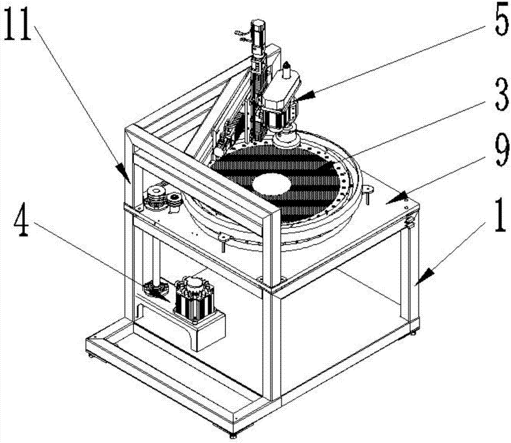
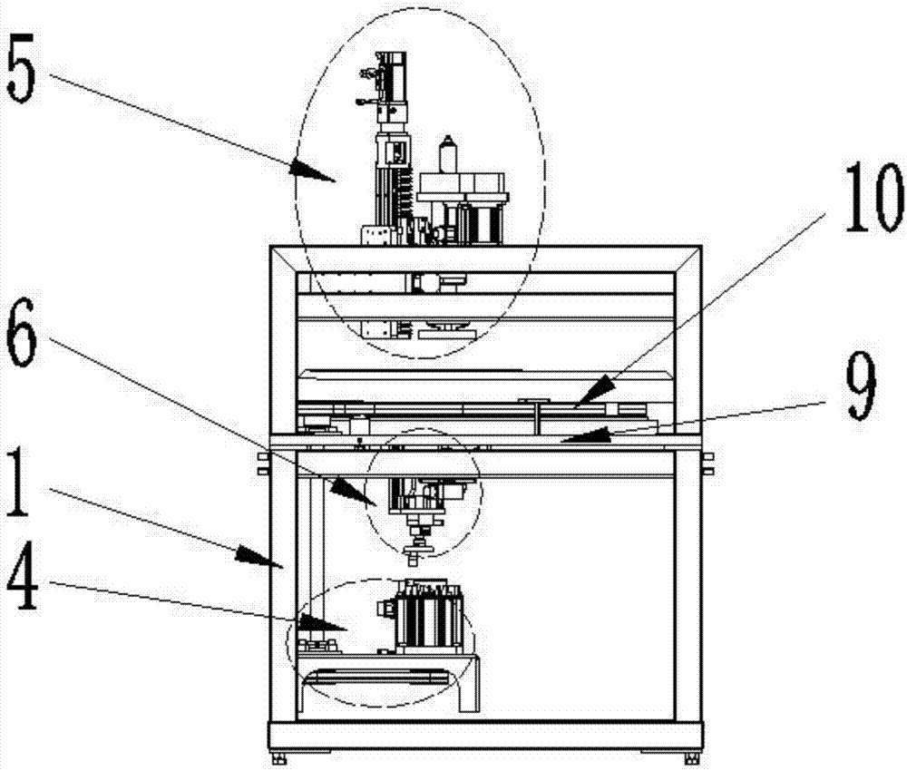
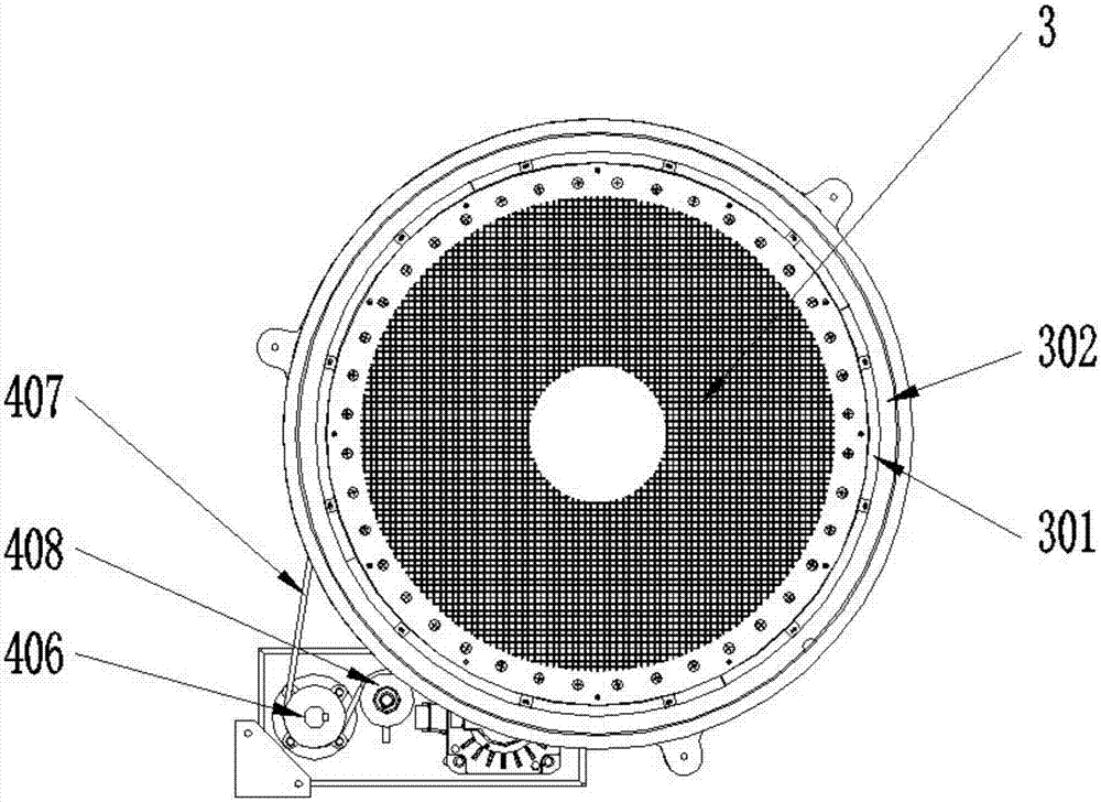
The invention provides a magneto-rheological plane polishing device and relates to the technical field of ultra-precision machining. The magneto-rheological plane polishing device comprises a bracket. A platform is arranged at the top end of the bracket. A rotating seat is fixed to the platform. A polishing disc is arranged on the rotating seat. A polishing disc driving mechanism is connected to the rotating seat. A workpiece clamping mechanism is arranged above the polishing disc and provided with a chuck. A magnetic field generating mechanism is arranged below the platform. A plurality of permanent magnets are uniformly arranged along the uniform-speed spiral on a rotating disc with the center of the rotating disc as a starting point. According to the magneto-rheological plane polishing device, the permanent magnets are alternately arranged on the rotating disc along the uniform-speed spiral in the mode that the directions of magnetic poles are opposite, and magneto-rheological polishing fluid forms a flexible polishing surface under the rotating composite action of the polishing disc, a to-be-machined workpiece and the permanent magnets; and real-time rapid updating self-sharpening is achieved on abrasive materials in the magneto-rheological polishing fluid under the action of a pulsed magnetic field, so that the magneto-rheological polishing efficiency is improved, the abrasion rate of abrasive particles in the polishing fluid is decreased, the service life of the magneto-rheological polishing fluid is prolonged, and the polishing efficiency and quality are improved.

Description

technical field [0001] The invention relates to the technical field of ultra-precision processing, in particular to a magneto-rheological plane polishing device, which is particularly suitable for ultra-smooth plane machining of microelectronic semiconductor wafers. Background technique [0002] Magnetorheological polishing technology is a technology that uses the rheological properties of magnetorheological polishing fluid in a magnetic field to polish workpieces. Magnetorheological polishing fluid will undergo rheological phenomena in a gradient magnetic field to form a viscoplastic Bingham (Bingham) flexible protrusions, when the flexible protrusions are in contact with the surface of the workpiece to be processed and undergo relative movement, a large shear force will be generated on the surface of the workpiece, and the material will be polished under the action of abrasive particles in the magnetorheological polishing fluid. remove. [0003] Magnetorheological polishi...

Claims


Application Information

Patent Timeline
IPC IPC(8): B24B1/00
CPCB24B1/005
Inventor 李建勇樊文刚曹建国刘月明聂蒙朱朋哲易德福
Owner BEIJING JIAOTONG UNIV
Learn More