Polysilicon ingot furnace with diversion device

A polycrystalline silicon ingot furnace and a flow guiding device technology, which are applied in the directions of polycrystalline material growth, crystal growth, chemical instruments and methods, etc., can solve the problem that the automatic crystal growth process cannot be carried out normally, liquid silicon is difficult to form a rotating flow field, and crystal growth is difficult. Inconvenient speed measurement and other problems, to achieve the effect of reducing subcooling, uniform radial resistivity, and improving yield

Inactive Publication Date: 2017-11-24
陈鸽
View PDF13 Cites 2 Cited by
  • Summary
  • Abstract
  • Description
  • Claims
  • Application Information

AI Technical Summary

Problems solved by technology

To overcome the problems existing in the prior art: the carrier gas is concentratedly blown to a certain area on the surface of the liquid silicon, without the driving force distributed in the circumferential direction, it is difficult to form a swirling flow field in the liquid silicon; and the carrier gas takes away a large amount of heat from this area , resulting in local overcooling of the liquid silicon in this area, which promotes the nucleation and growth of impurities in the liquid silicon; It is convenient for the operation of the furnace; the crystal measuring rod cannot be inserted into the ingot casting furnace through the diversion device, and the crystal growth rate is inconvenient to measure; the infrared detector cannot detect the state of the silicon material in the furnace through the observation window, and the automatic crystal growth process cannot be carried out normally

Method used


Image

  • Polysilicon ingot furnace with diversion device
  • Polysilicon ingot furnace with diversion device
  • Polysilicon ingot furnace with diversion device

Examples


Embodiment approach 1

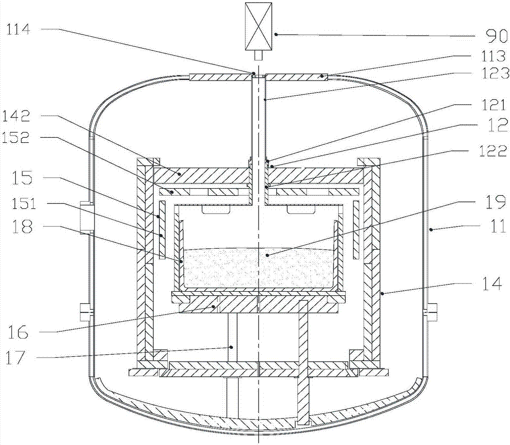
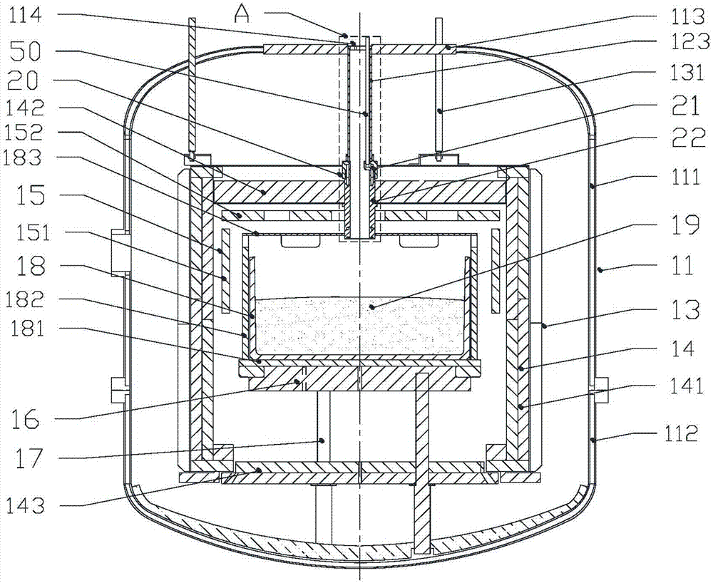
[0061] A kind of polysilicon ingot furnace with guide device of the present invention, as figure 2 As shown, the ingot casting furnace includes a furnace body 11, a cage frame 13, a lifting screw 131, a heat insulation cage 14, a heater 15, a heat exchange platform 16, a graphite column 17, a graphite tube 123, a gas delivery pipe 50 and a flow guide device 20. The furnace body 11 includes an upper furnace body 111 , a lower furnace body 112 and a top end cover 113 , the upper furnace body 111 covers the lower furnace body 112 , and the top end cover 113 covers the top opening of the upper furnace body 111 . Described cage frame 13 is made of 4 side walls, and top surface and bottom surface are open. The cage frame 13 is arranged in the furnace body 11 , and is suspended on the furnace roof of the upper furnace body 111 through a lifting screw 131 . The heat insulation cage 14 is a square cavity composed of four side heat insulation panels 141 , one top insulation panel 142...

Embodiment approach 2

[0070] A kind of polysilicon ingot furnace with guide device of the present invention, as Figure 9 As shown, the ingot casting furnace includes a furnace body 11, a guide assembly 12, a cage frame 13, a lifting screw 131, a heat insulation cage 14, a heater 15, a heat exchange platform 16, a graphite column 17, a gas pipe 50 and a guide Flow device 30. The furnace body 11 comprises an upper furnace body 111, a lower furnace body 112 and a top end cover 113. The upper furnace body 111 is covered on the lower furnace body 112, and the top end cover 113 is covered on the top opening of the upper furnace body 111. The top end cover 113 There is an observation window 114 in the middle. The cage 13 is composed of four sidewalls, the top and the bottom are open, and the cage 13 is suspended on the furnace roof of the upper furnace body 111 through a lifting screw 131 . The heat insulation cage 14 is a square cavity composed of four side heat insulation panels 141 , one top insulat...

Embodiment approach 3

[0078] A kind of polysilicon ingot furnace with guide device of the present invention, as Figure 16 As shown, the polysilicon ingot casting furnace includes a furnace body 11, a guide assembly 12, a cage frame 13, a lifting screw 131, a heat insulation cage 14, a heater 15, a heat exchange platform 16, a graphite column 17, a gas delivery pipe 50 and Flow guiding device 40. The furnace body 11 comprises an upper furnace body 111, a lower furnace body 112 and a top end cover 113. The upper furnace body 111 is covered on the lower furnace body 112, and the top end cover 113 is covered on the top opening of the upper furnace body 111. The top end cover 113 There is an observation window 114 in the middle. The cage 13 is composed of four sidewalls, the top and the bottom are open, and the cage 13 is suspended on the furnace roof of the upper furnace body 111 through a lifting screw 131 . The heat insulation cage 14 is a square cavity composed of four side heat insulation panels...


PUM


Abstract

The invention discloses a polysilicon ingot furnace with a diversion device. The polysilicon ingot furnace comprises a heat insulation cage, a gas pipe and a diversion device. The diversion device is equipped with multiple diversion airways used for dividing input carrier gas into multiple outgoing carrier gas flows. The carrier gas flows are dispersedly and slantly blown to different areas on the surface of liquid silicon, thus effectively increasing contact area of the carrier gas and the surface of liquid silicon and minimizing heat per unit area by carrier gas flow. Thermal drop of liquid silicon in the area is reduced, degree of supercooling is decreased, and impurity nucleation and impurity formation caused by carrier gas are reduced. The outgoing carrier gas flows produce carrier gas stress to liquid silicon so as to drive liquid silicon to flow and to form a rotary flow field for circumferential flow. The rotary flow field is beneficial to transportation and uniform distribution of impurities in liquid silicon. An observation window at the top of the furnace has a field of view leading to the ingot furnace via the diversion device. Through the observation window, state inside the furnace can be observed, and a crystal measurement rod is inserted into the furnace. An infrared detector can detect the state of silicon materials inside the furnace, and the automatic crystal growth process is smoothly carried out.

Description

[0001] This application is a divisional application of a patent application with the application number 201610082954.0, the application date is 2016-02-03, and the name is a polycrystalline silicon ingot furnace with a flow guiding device. technical field [0002] The invention relates to a polysilicon ingot furnace, in particular to a polysilicon ingot furnace with a diversion device for changing the direction of carrier gas, and belongs to the field of crystal growth equipment. Background technique [0003] The polycrystalline silicon ingot casting furnace is mainly composed of an infrared detector 90, a furnace body 11, a flow guiding device 12, a heat insulation cage 14, a heater 15, a heat exchange platform 16 and a graphite column 17, such as figure 1 As shown, the middle part of the end cover 113 on the furnace body 11 is provided with an observation window 114 . The heater 15 includes side heaters 151 and top heaters 152 on four sides. The flow guiding device 12 inc...

Claims


Application Information

Patent Timeline
Patent Type & Authority Applications(China)
IPC IPC(8): C30B28/06C30B29/06
CPCC30B28/06C30B29/06
Inventor 陈鸽其他发明人请求不公开姓名
Owner 陈鸽
Why Eureka
Try Eureka