
Method for measuring light spot drift and light beam jitter via spherical mirror reflection

A technology of reflection measurement and beam shaking, which is applied in the field of wireless optical communication, can solve the problems of inconvenient atmospheric turbulent beam expansion spot drift measurement and analysis

Inactive Publication Date: 2017-11-24
XIAN UNIV OF TECH
View PDF1 Cites 10 Cited by
  • Summary
  • Abstract
  • Description
  • Claims
  • Application Information

AI Technical Summary

Problems solved by technology

However, the beam expansion obtained by existing measurement methods is a small amount, which is not convenient for measuring and analyzing the beam expansion and spot drift in atmospheric turbulence

Method used


Image

  • Method for measuring light spot drift and light beam jitter via spherical mirror reflection
  • Method for measuring light spot drift and light beam jitter via spherical mirror reflection
  • Method for measuring light spot drift and light beam jitter via spherical mirror reflection

Examples


Embodiment Construction

[0111] The present invention will be described in detail below in conjunction with the accompanying drawings and specific embodiments.

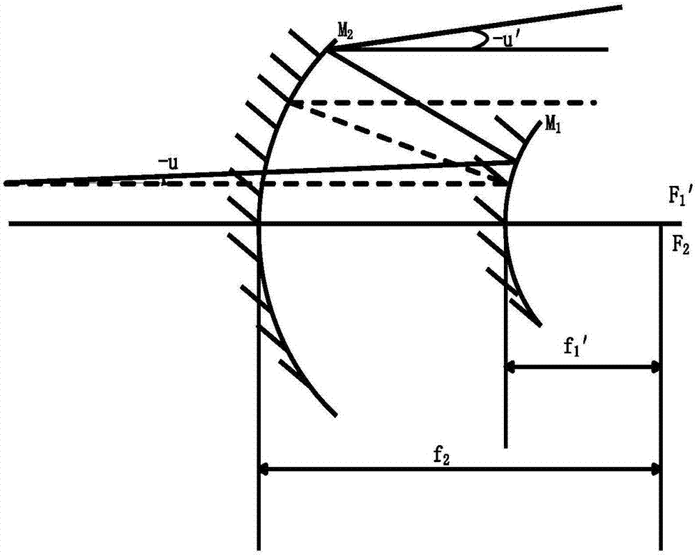
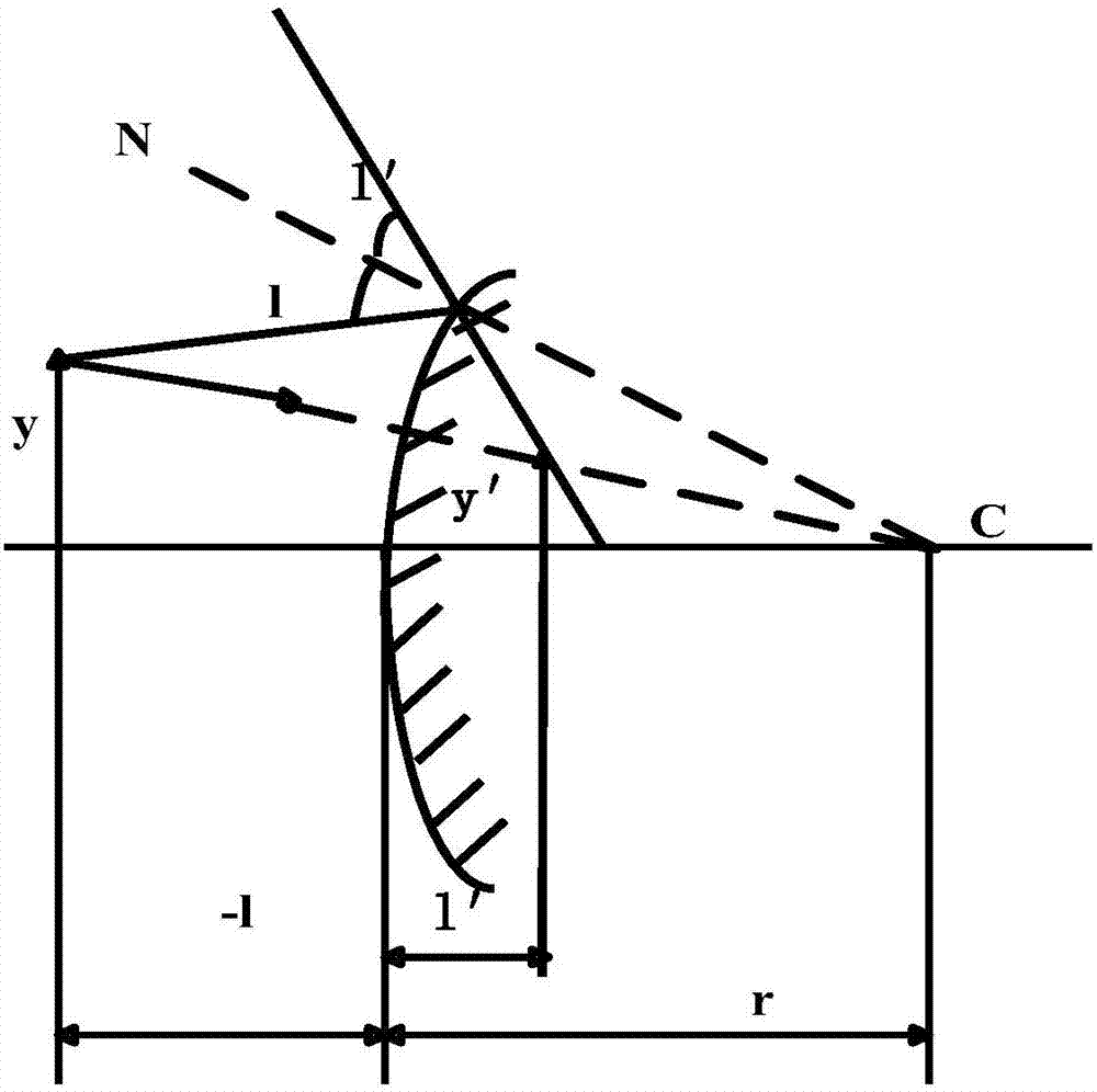
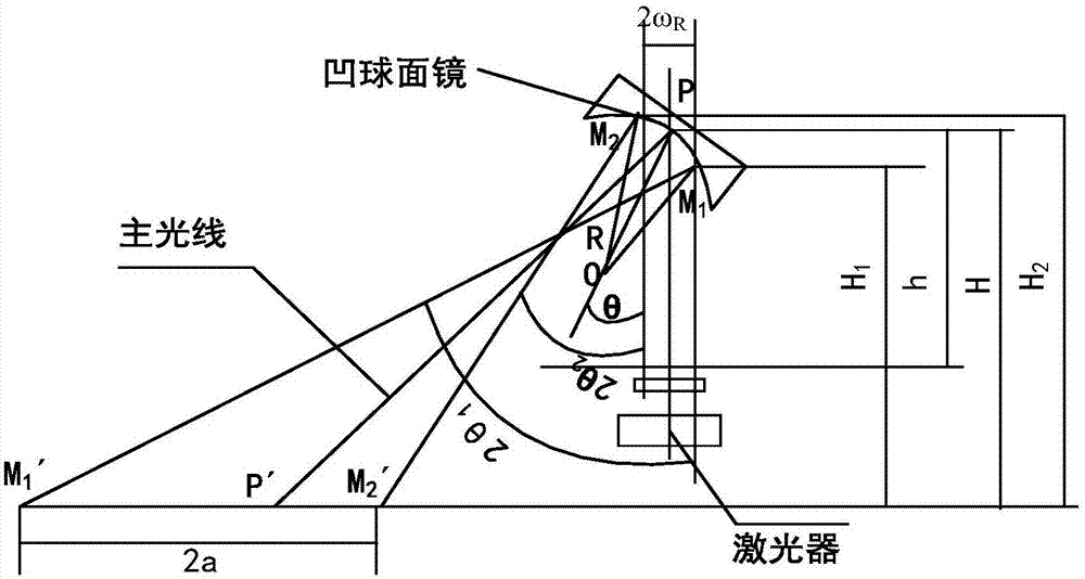
[0112] The present invention is a method for measuring spot drift and beam jitter using spherical mirror reflection. The method is based on a focusing system, a beam expander system and a laser collimation system. The method is specifically implemented according to the following steps:

[0113] Step 1. Use a laser focusing system (such as: laser hole processing, optical disc reading and writing, etc.) to converge the laser beam into tiny light spots;

[0114] If other optical systems (such as microscopes) are used, although the purpose of focusing can also be achieved, due to the consideration of chromatic aberration, off-axis aberration, etc., the structure is complex and there are many refraction surfaces, and the defects in optical materials have very high requirements for energy density. High coherent light is unfavorable, it will cause l...


PUM


Abstract

The invention discloses a method for measuring light spot drift and light beam jitter via spherical mirror reflection. The method comprises the following steps: in a first step, laser light beams are gathered into tiny light spots via a laser focusing system; in a second step, a beam expanding system is used for performing beam expanding operation on the light beams output via the laser focusing system in the first step; in a third step, to improve directivity of the light beams, a divergence angle of the laser light beams is compressed after the beam expanding operation is performed on the laser light beams in the second step, and a laser light alignment system is built; in a fourth step, a reflection law is regarded as regarded as a refraction law in a special condition where n equals -n ', and a diameter of a light spot formed on an optical screen in the third step is calculated; in a fifth step, a spherical mirror reflection model is built according to principles in the fourth step, the light spot on the optical screen is approximated to an ellipse, a short axis length and a long axis length of the light spot obtained via the spherical mirror reflection are calculated, and therefore the light spot drift and the light beam jitter can be obtained. Via the method disclosed in the invention, light beam expansion and light spot drift in atmosphere turbulences can be measured and analyzed.

Description

technical field [0001] The invention belongs to the technical field of wireless optical communication, relates to a measurement system, in particular to a method for measuring light spot drift and light beam jitter by using spherical mirror reflection. Background technique [0002] In atmospheric laser communication, the influence of the characteristics of the atmospheric channel on the communication system is very important. Due to the continuous fluctuation of the atmospheric refractive index in the atmospheric turbulence, the light wave parameters will change randomly during the laser transmission process, resulting in the spot in the communication process. Phenomena such as drift, intensity fluctuations, and beam expansion. In order to understand and analyze these phenomena, an atmospheric turbulence effect model can be established, and a specific experimental device can be used to study the influence of atmospheric turbulence on laser beam transmission. However, the be...

Claims


Application Information

Patent Timeline
IPC IPC(8): G01S7/52
CPCG01S7/52004
Inventor 吴鹏飞贾璐瑶张启东
Owner XIAN UNIV OF TECH
Learn More