Two-sided heat dissipation power module of laminated substrates

A double-sided heat dissipation, power module technology, applied in electrical components, electrical solid devices, circuits, etc., can solve the problems of hindering power density, chip overvoltage breakdown, parasitic inductance difficulty, etc., to reduce the area of ​​the commutation loop, The effect of increasing the area of ​​the metal layer and reducing the lead resistance

Pending Publication Date: 2017-11-24
YANGZHOU GUOYANG ELECTRONICS CO LTD
View PDF3 Cites 10 Cited by
  • Summary
  • Abstract
  • Description
  • Claims
  • Application Information

AI Technical Summary

Problems solved by technology

Existing power electronic power modules have large packages and heavy weights, which do not meet the requirements of high power density and light weight of power electronic modules, and the parasitic inductance of existing power modules is often relatively large, resulting in high overshoot voltage, which not only increases It reduces loss, and it is easy to cause chip overvoltage breakdown, which also limits the application in high switching frequency occasions
In addition, with the continuous upgrading of power density at the application end, the packaging structure of existing power modules has hindered the further improvement of power density, and a more effective heat dissipation structure must be developed to meet the increasing demand for power density
[0003] In recent years, people have gradually realized the limitations of parasitic inductance of power modules on high-frequency applications, and have conducted research on how to reduce the parasitic inductance of power modules. There are very few studies on the shape and position of power terminals
The positive and negative power terminals of existing double-sided heat dissipation power modules often adopt a side-by-side lead-out structure. The commutation circuit of this structure is relatively large, and it is difficult to further reduce the parasitic inductance; and through a large number of simulations and tests, the positive and negative power terminals have been verified. The combination form has a great influence on the parasitic inductance of the power module

Method used


Image

  • Two-sided heat dissipation power module of laminated substrates
  • Two-sided heat dissipation power module of laminated substrates
  • Two-sided heat dissipation power module of laminated substrates

Examples


Embodiment 1

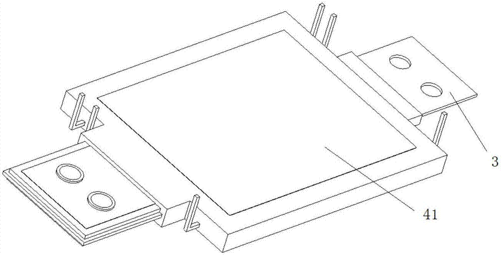
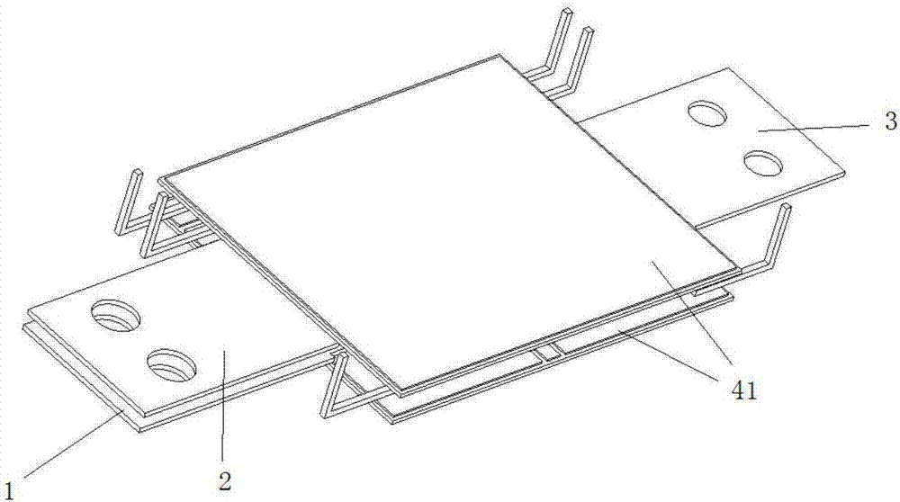
[0030] Such as figure 1 As shown, a double-sided heat dissipation power module with a laminated substrate includes a positive power terminal 1, a negative power terminal 2, and an output power terminal 3. The positive power terminal 1 and the negative power terminal 2 are each connected to an outer metal insulating substrate 41, as shown in FIG. It can be seen that the outer metal insulating substrate 41 at the top is connected to the negative power terminal 2 , and the outer metal insulating substrate 41 at the bottom is connected to the positive power terminal 1 .

[0031] Two outer metal insulating substrates 41 are stacked, and a chip is sintered on the outer metal insulating substrate 41 connected to the positive power terminal 1; the middle metal insulating substrate 42 is arranged on the outer metal insulating substrate 41 connected to the negative power terminal 2; The metal block 5 is sintered with the metal insulating substrate opposite to it.

[0032] The positive ...

Embodiment 2

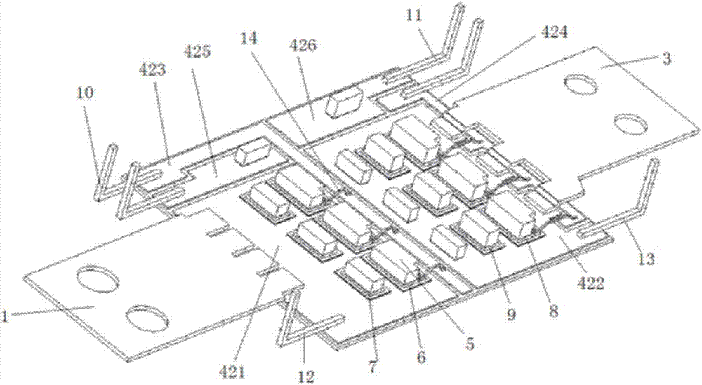
[0044] Such as Figure 9 , Figure 10 As shown, the structure of this embodiment is basically the same as that of Embodiment 1, the difference is that in this embodiment, the outer metal insulating substrate 41 connected to the positive power terminal 1 is provided with an intermediate metal insulating substrate 42 and the intermediate metal insulating substrate 42 There are also chips sintered on it, the chips set on the outer metal insulating substrate 41 connected to the positive power terminal 1 are the upper half-bridge switch chip 6 and the upper half-bridge diode chip 7, and the chips set on the middle metal insulating substrate 42 are the lower half-bridge A switch chip 8 and a lower half-bridge diode chip 9 . The specific configuration of the metal layers is shown in the figure, and the specific names and connection methods of each metal layer can be set according to the routine by those skilled in the art with reference to Embodiment 1, and will not be repeated here...

Embodiment 3

[0046] The structure of this embodiment is basically the same as that of Embodiment 1. The difference is that the intermediate metal insulating substrate 42 in this embodiment includes an insulating layer and two metal layers respectively arranged on both sides of the insulating layer, and one metal layer is insulated from the outer metal. The substrate 41 is adjacent, and chips or metal blocks are sintered on another metal layer.


PUM


Abstract

The invention discloses a two-sided heat dissipation power module of laminated substrates. The power module comprises a positive power terminal, a negative power terminal and an output power terminal. Each of the positive power terminal and the negative power terminal is connected with an outer insulating metal substrate. The two outer insulating metal substrates are arranged in a laminated mode. The outer insulating metal substrate connected with the positive power terminal is sintered with a chip. A middle insulating metal substrate is arranged on the outer insulating metal substrate connected with the negative power terminal. According to the two-sided heat dissipation power module of the laminated substrates, the two outer insulating metal substrates are arranged in the laminated mode, the middle insulating substrate is combined to be matched with sintering design of a metal layer and a metal block inside the power module, so that the commutation circuit area is reduced, and the parasitic inductance of the module is significantly reduced; besides, the positive power terminal and the negative power terminal are arranged in a laminated mode, so that the terminals are easily connected with an external busbar; the lead resistance is extremely low, the area of the metal layer is increased as far as possible, the lead resistance of the module is effectively reduced, and the purpose of significant reduction of the parasitic inductance is achieved.

Description

technical field [0001] The invention relates to a power semiconductor module, in particular to a power module with heat dissipation on both sides of a stacked substrate. Background technique [0002] The global energy crisis and the threat of climate warming make people pay more and more attention to energy conservation, emission reduction and low-carbon development while pursuing economic development. With the establishment and promotion of green environmental protection in the world, the development and application prospects of power semiconductors are broader. Existing power electronic power modules have large packages and heavy weights, which do not meet the requirements of high power density and light weight of power electronic modules, and the parasitic inductance of existing power modules is often relatively large, resulting in high overshoot voltage, which not only increases It increases the loss, and it is easy to cause chip overvoltage breakdown, which also limits...

Claims


Application Information

Patent Timeline
Patent Type & Authority Applications(China)
IPC IPC(8): H01L23/498H01L25/07
CPCH01L23/49811H01L23/49838H01L25/072H01L2224/33H01L2224/2612H01L2224/32225H01L2224/0603H01L2224/48227H01L2224/33181
Inventor 滕鹤松徐文辉王玉林
Owner YANGZHOU GUOYANG ELECTRONICS CO LTD
Why Eureka
Try Eureka