[0022] The following will clearly and completely describe the technical solutions in the embodiments of the present invention with reference to the accompanying drawings in the embodiments of the present invention. Obviously, the described embodiments are only some, not all, embodiments of the present invention. Based on the embodiments of the present invention, all other embodiments obtained by persons of ordinary skill in the art without making creative efforts belong to the protection scope of the present invention.
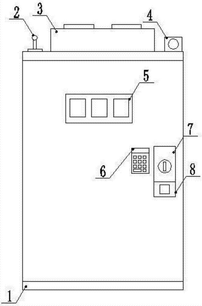
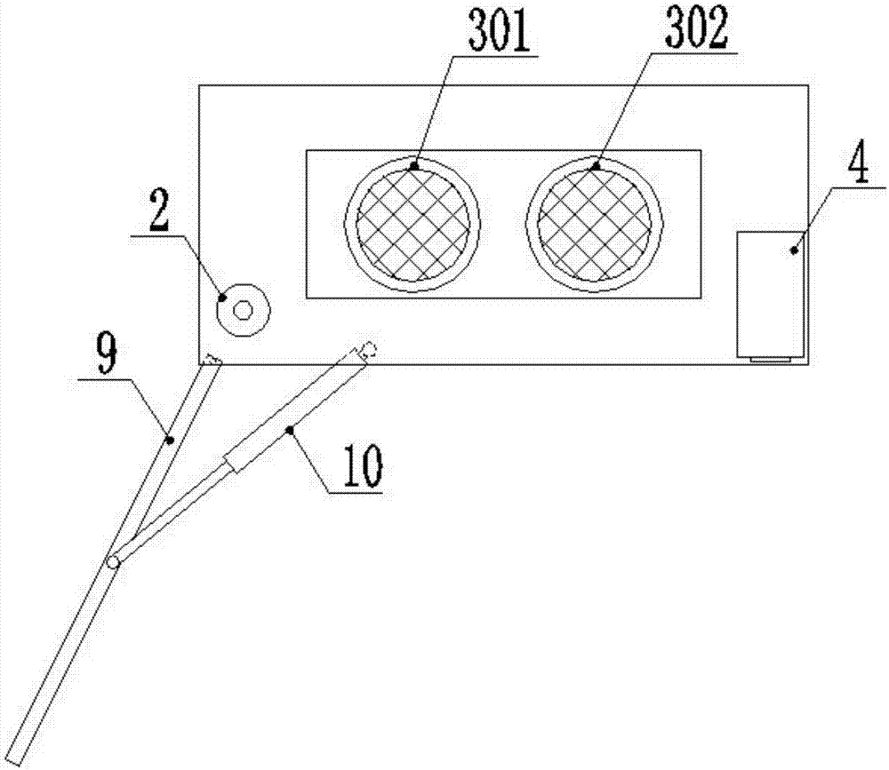
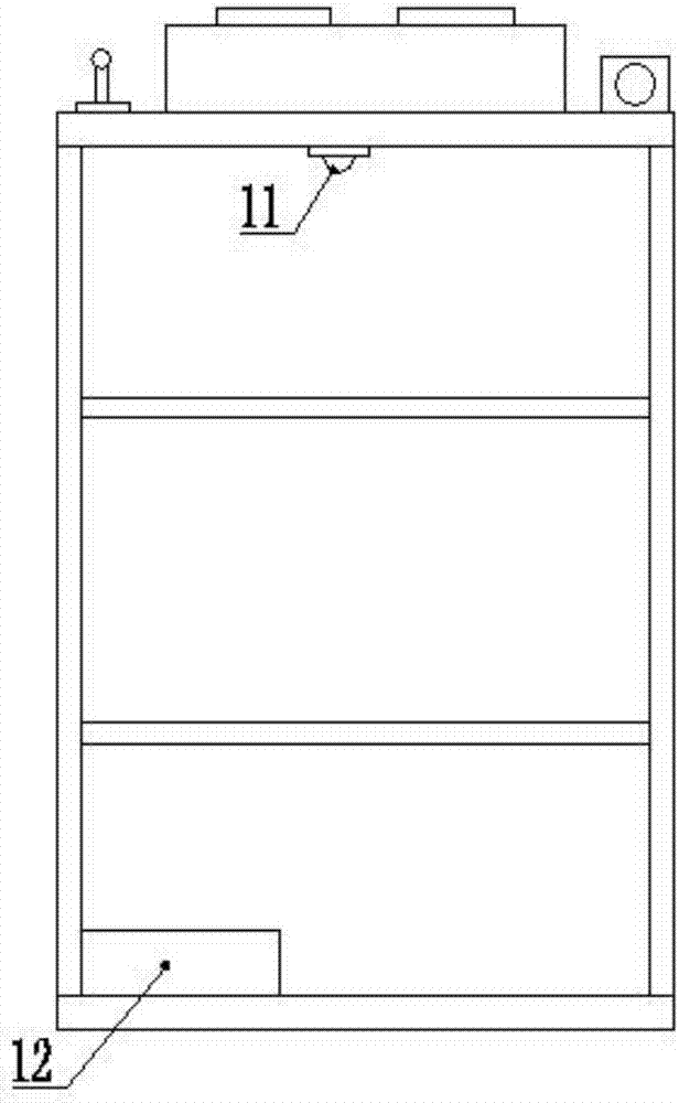
[0023] see Figure 1-5 , an intelligent high and low voltage switch cabinet capable of remote monitoring, including a switch cabinet body 1, which is rectangular in shape, including a skeleton and a skin. The skeleton is composed of rectangular tube profiles horizontally and vertically. There are standard connection holes evenly arranged on the profile, and the skin is a thin steel sheet metal part, which is fixed on the skeleton, and there are first heat dissipation through holes, second heat dissipation through holes and ball hinge connection holes on the top, the first heat dissipation through holes and The second radiating through holes are symmetrically arranged left and right, and the ball hinge connection holes are arranged near the door opening of the switch cabinet body 1. The first louver 101 and the second louver are arranged on the left side of the skin from top to bottom. Window 102 and the 3rd louver 103, they are evenly spaced, the specification is the same, in the 1st louver 101, the second louver 102 and the 3rd louver 103 inside are equipped with dust-proof net, on skin Shutters are also arranged on the right side of the switch cabinet. Its specifications and layout are the same as those on the left side. An LED communication device 2 is fixed on the left side of the top of the switch cabinet body 1, which includes a processing device, an LED signal transceiver, and a processing device. Including protective case and processor, the shape of the protective case is round, its material is ABS engineering plastics, protection grade IP67, the processor is installed inside the protective case, it includes processing chip, frequency converter, frequency generator and control circuit, the LED signal transceiver is arranged on the top of the processing device, which includes an LED signal light and a photosensitive camera, the LED signal light is connected to the frequency generator, the frequency generator is connected to the processing chip, the photosensitive camera is connected to the frequency converter, and the frequency converter is connected to the processing chip. The chips are connected, and LED light groups and LED frequency converters are also arranged at the place where the high and low voltage switchgear is installed. The LED light groups include LED lights and signal receivers. Each LED light group is connected to the LED frequency converter. Connected to form LED optical signal communication, a cooling device 3 is arranged on the right side of the LED communication device 2, and it includes a first frequency conversion cooling fan 301 and a second frequency conversion cooling fan 301, which are symmetrically arranged on the left and right sides of the cooling device 3 respectively. A frequency conversion cooling fan 301 is located above the first cooling through hole of the skin, and a first dustproof net is also installed on the first cooling through hole, and a second frequency conversion cooling fan 302 is located above the second cooling through hole of the skin. A second dust-proof net is also installed on the second cooling through hole. The first variable frequency cooling fan 301 and the second variable frequency cooling fan 302 are of the same type. Camera device 4, it comprises camera, alarm device and image processing unit, and alarm device comprises alarm and alarm feedback module, and alarm feedback module is connected with background control center, and image processing unit comprises facial recognition chip and storage unit, and storage unit prestores user The facial biometric information, the facial recognition chip is connected with the camera to collect the user’s facial image features, it is also connected to the storage unit, reads the pre-stored facial biometric information, and performs matching. Body monitoring device 11, it comprises temperature sensor and humidity sensor, monitors in the cabinet An electric push rod 10 is also installed next to the device 11, and a cabinet drive device 12 is fixed on the bottom surface of the switch cabinet body 1, which includes a drive device protective case, a control circuit, a drive control chip and a wired communication device, and the electric push rod The tail of the fixed end of 10 is a spherical hinge structure, which is connected to the spherical hinge connecting hole of the skin, and the top of its push rod is also a spherical hinge structure, which is connected to the cabinet door 9, and the shape of the cabinet door 9 is a cuboid. Including the outer layer and the inner layer, the material and color are the same as the skin, and there is a ball hinge hole on the top, which is connected with the ball hinge on the top of the electric push rod 10, and the instrument area 5 is arranged on the outer surface of the outer layer , there are three known instrument panels above it, and a password input device 6 is arranged at the bottom right of the instrument area 5, which includes a password display screen and a password button, and the password button includes 0 to 9 numeric keys, a determination key and a delete key, in the password On the right side of the input area 6, there is a key area 7. Below the key area 7 is a fingerprint unlocker 8. The cabinet door 9 has four ways of password unlocking, key unlocking, fingerprint unlocking and facial feature unlocking. Any two ways of unlocking are successful. The door can be opened, and the password to unlock the password is 6 digits. The fingerprint unlocking and facial feature unlocking need to initialize and save the fingerprint and facial feature information. The first ball screw 915 is installed on the far right side of the layer, the first bevel gear 910 is fixed below it, and tapered roller bearings are also installed at its upper and lower ends, and match with the bearing holes of the cabinet door 9, the first The meshing gear of the bevel gear 910 is the second bevel gear 911, its tail shaft is equipped with a deep groove ball bearing, and is fixed on the bearing hole of the first L-shaped plate 909, and the first L-shaped plate 909 is fixed on the second bevel gear On the left side of 911, a first motor plate 907 is fixed on the left side of the first L-shaped plate 909, a motor shaft through hole is arranged on its vertical plate, and a first servo motor 906 is fixed on the left side of its vertical plate, and its protruding The shaft is connected to the tail shaft of the second bevel gear 911 through the first coupling 908, and a sliding seat 903 is installed between the guide rod 901 and the first ball screw 915, and there is a through hole on the left and right sides of the sliding seat 903. A guide sleeve 902 is installed on the through hole on the right, and a first ball screw sleeve 916 is installed on the right through hole. The guide sleeve 902 is a stepped shaft, and its center has a guide hole coaxial with the outer shaft. Its material is copper. The outer shaft of the outer shaft matches the left hole of the sliding seat 903, and its guide hole matches the guide rod 901. The first ball screw sleeve 916 is a stepped shaft, and its center has a screw hole coaxial with the outer shaft. The shaft matches the right hole of the sliding seat 903, and its screw hole matches the first ball screw sleeve 916. On the outer surface of the sliding seat 903, a first guide rail 918 and a second guide rail 904 are symmetrically arranged up and down. The left side of 903 outer surfaces is fixed with a left L-shaped plate, and the right side is fixed with a right L-shaped plate 917. There are bearing holes on their vertical plates, and tapered roller bearings are installed back to back, and the second tapered roller bearing is installed between the two tapered roller bearings. Two ball screw rods 905 are fixed with a second motor plate 913 on the right side of the right L-shaped plate 917, and a motor overpass is arranged on the vertical plate of the second motor plate 913. hole, and is fixed with a second servo motor 914, its extension shaft is connected with the right end of the second ball screw 905 through the second coupling 912, and a sliding plate 920 is also installed on the second ball screw 905, its The bottom is symmetrically arranged with sliders up and down, which are respectively matched with the first guide rail 918 and the second guide rail 904, and there is also a ball screw seat in the middle of the bottom of the slide plate 920, which matches the second ball screw 905, on the slide plate 920 There is also a temperature measuring device 919 on the top, which includes a thermal imaging camera, a laser range finder, an industrial camera and an obstacle avoidance sensor. The thermal imaging camera measures the operating temperature of electrical equipment, and the laser range finder measures Measuring the distance between electrical equipment, recording the internal status of high and low voltage switch cabinets with industrial cameras, and feeding back the obstacle information in front of the obstacle avoidance sensor, the drive control chip of the drive device 12 and the electric push rod 10 in the switch cabinet cabinet 1, the first servo The motor 906, the second servo motor 914, the first frequency conversion cooling fan 301 and the second frequency conversion cooling fan 302 are connected, the processing chip in the LED communication device 2 is connected with the drive control chip, and the control command is transmitted to the drive control chip, and the processing chip and temperature The measuring device 919, the cabinet monitoring device 11 is connected with the monitoring camera device, and the state information of the high and low voltage switch cabinet is sent to the background control center through the LED light signal to realize remote control and monitoring.
[0024] During use, there are four unlocking methods for the operation and maintenance personnel to open the cabinet door 9, which are password encryption, key lock, fingerprint encryption and facial feature encryption. The door can be opened by any two unlocking methods. After the cabinet door 9 is opened, The camera on the monitoring camera device 4 collects the image features of the unlocking person in real time. When there is an inconsistency between the image features of other operators and the pre-stored authorized personnel in the middle, the internal alarm will alarm and feed back information to the background through the internal alarm feedback module. The situation of the switchgear can be grasped in time; the LED communication device 2 on the switchgear body forms an LED optical signal communication with the LED light group and the LED frequency converter around the cabinet body, and the background control center can communicate with each switchgear body through optical signals The processing chip in the LED communication device 2 receives the remote control command converted by the frequency converter, it is connected with the drive control chip, and the drive control chip receives the identifiable remote command to control the electric push rod 10, the first Servo motor 906, the second servo motor 914, the first frequency conversion cooling fan 301 and the second frequency conversion cooling fan 302 actions; For the working temperature of electrical equipment, the laser range finder measures the distance between the thermal imager and the electrical equipment under test, while the cabinet monitoring device 11 measures the temperature and humidity data of the switch cabinet, which is transmitted by communication in the background, and can be comprehensively analyzed after obtaining the data The actual operating temperature of the device under test can be compared with the normal operating temperature of the device under test to determine whether the device is faulty. When the device under test is continuously measured, it can also predict the potential fault of the device. The temperature measuring device 919 passes The second servo motor 914, the first guide rail 918, the second guide rail 904, and the second ball screw 905 cooperate to move freely in the horizontal direction, through the first servo motor 906, the first bevel gear 910, and the second bevel gear 911 , the cooperation of the first ball screw 915 and the sliding seat 903 can move freely in the vertical direction, and the background can perform remote measurement on all position devices in the switch cabinet.
[0025]To sum up: the remote monitoring intelligent high and low voltage switchgear, through the LED communication device 2 on the switchgear body 1, forms LED light signal communication with the LED light group and LED frequency converter around the switchgear body, so that the background control center It can be connected to each switch cabinet body 1 through optical signals, and at the same time, the various cabinets can also be connected to each other through LED optical signal communication to transmit data to each other. Compared with traditional wireless network connections, the communication is stable and fast. Small size, long-distance and high-efficiency wireless transmission, at the same time, the wired communication device in the drive device of the switchgear cabinet 1 can also be connected to the wired network, so that the communication of the switchgear cabinet 1 has a double guarantee to meet the use under different conditions. The processing chip in the LED communication device 2 is connected with the photosensitive camera and the frequency converter, and can receive converted remote control commands. The processing chip is connected with the drive control chip. The drive control chip receives recognizable remote commands, and the drive control chip communicates with The electric push rod 10, the first servo motor 906, the second servo motor 914, the first frequency conversion cooling fan 301 and the second frequency conversion cooling fan 302 are connected to complete remote operation and realize remote control of the switch cabinet. In contrast, operation and maintenance personnel do not need to go to the site in person, they can remotely complete the basic operation of the switch cabinet, making the control more convenient and fast. The cabinet door 9 has four methods: password encryption, key lock, fingerprint encryption and facial feature encryption. Any two unlocking methods can be used to open the door, which realizes the diversification of the switch cabinet protection and encryption methods and improves the security. Compared with the traditional single key lock, the use of more secure and diversified unlocking methods prevents the key from being lost and cannot be locked. When it is opened, the camera on the monitoring camera device will collect the image features of the unlocking person in real time. When it is inconsistent with the image features of the pre-stored person, the alarm will be sent to the police, and the information will be fed back to the background through the alarm feedback module, so that the background can grasp the safety of the switch cabinet in time. The working temperature of the electrical equipment is measured by the infrared thermal imager on the temperature measuring device 919, the distance between the infrared thermal imager and the electrical equipment under test is measured by the laser rangefinder, and the temperature and humidity data of the switchgear is measured by the cabinet monitoring device 11 , can comprehensively analyze the actual operating temperature of the equipment under test. By comparing it with the normal operating temperature of the equipment under test, it can be judged whether the equipment is faulty. At the same time, the continuous measurement of the equipment under test can also predict the potential failure of the equipment. Communication transmission, the background can remotely grasp the working status and health status of all equipment in the switch cabinet. Compared with the traditional switch cabinet, you can keep abreast of the status of the equipment without going to the site in person, reducing manpower and material resources, and at the same time predicting the equipment , and the maintenance and replacement plan can also be done in time to prevent the equipment from suddenly breaking down and causing unnecessary losses. By installing the temperature measuring device 919 on the sliding plate 920, and passing the second servo motor 914, the first guide rail 918, and the second The guide rail 904 and the second ball screw 905 can make the temperature measuring device 919 move arbitrarily in the horizontal direction, through the first servo motor 906, the first bevel gear 910 , the second bevel gear 911, the first ball screw 915, and the sliding seat 903 can realize the arbitrary movement of the temperature measuring device 919 in the vertical direction, which meets the requirements of the temperature measuring device 919 for measuring all position equipment in the switch cabinet, and realizes Automation and full coverage of remote monitoring.
[0026] Although the embodiments of the present invention have been shown and described, those skilled in the art can understand that various changes, modifications and substitutions can be made to these embodiments without departing from the principle and spirit of the present invention. and modifications, the scope of the invention is defined by the appended claims and their equivalents.