PE micro-porous filter

A microporous filter and microporous filtration technology, which is applied in the direction of membrane filter, fixed filter element filter, filtration separation, etc., can solve the problem of increasing the radial compressive strength, reducing the easy damage value of the tube, reducing the wall thickness, etc. problems, to achieve the effect of increasing the radial compressive strength, reducing the easy damage value of the tube, and improving the durability

Pending Publication Date: 2017-11-28
王家骐
View PDF6 Cites 3 Cited by
  • Summary
  • Abstract
  • Description
  • Claims
  • Application Information

AI Technical Summary

Problems solved by technology

In this way, the small-diameter microporous filter tube has the advantages of small circumference ratio, increased radial compressive strength, reduced wall thickness, and low resistance of the filter tube. A bundle tube group composed of multiple microporous filter tubes can effectively solve the problem of small-aperture and thin-walled tubes. The number of microporous filter tubes is insufficient in rigidity due to the small number, reducing the tube's easy damage value, increasing the number of tubes per unit section to effectively increase the unit section of the filtration area, making the power consumption of filtration and backwashing small, and the kinematic viscosity of the filtrate If it is not very large, the flushing of compressed air can be omitted, and only the backwash of the clear liquid in the clear liquid tank can be used to backwash, which improves durability, saves costs, and is convenient for manual installation and maintenance; The microporous filter tubes are installed inside, so that these microporous filter tubes form a bundle tube group, and the bundle tube fixing rings are arranged separately to strengthen its pressure resistance, so that the overall use stability of the filter part is good

Method used


Image

  • PE micro-porous filter
  • PE micro-porous filter
  • PE micro-porous filter

Examples


Embodiment Construction

[0030] The present invention will be further described below in conjunction with accompanying drawing:

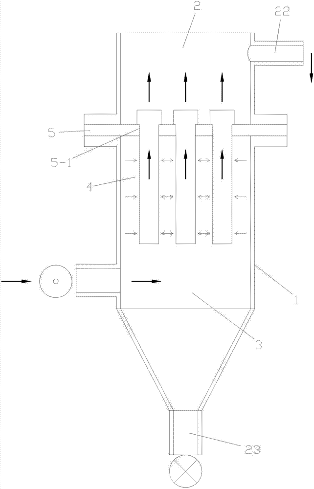
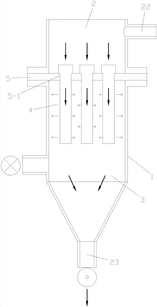
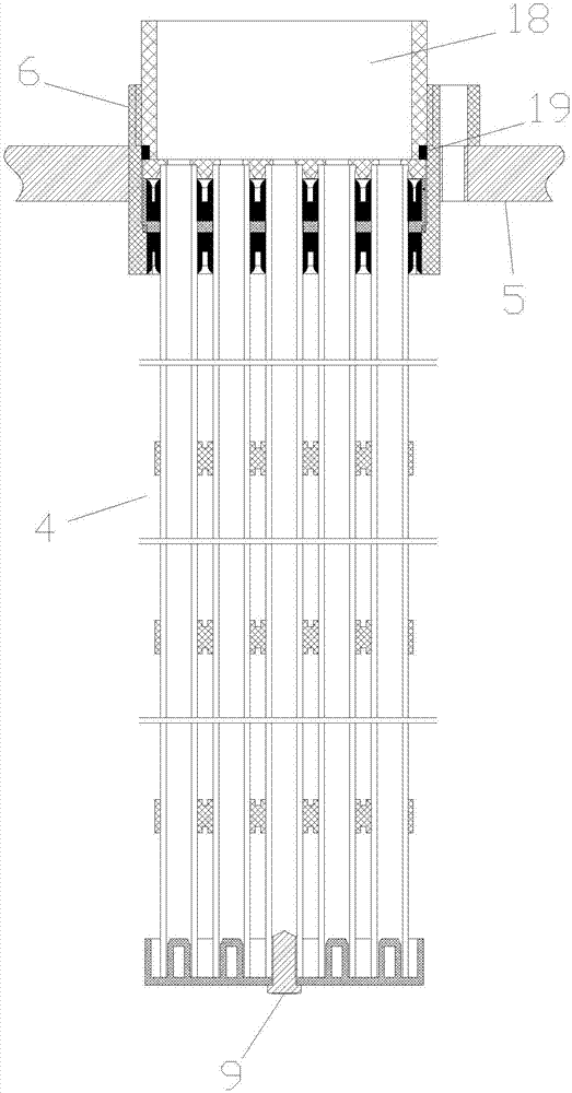
[0031] Referring to the accompanying drawings: this PE microporous filter includes a filter container 1, and the filter container 1 is provided with a clear liquid tank 2, a filter tank 3, a group of filter parts 4, and locking coils installed outside these filter parts 4 6 and the fixed plate 5 installed in the filter container 1, the fixed plate 5 is provided with an installation port 5-1 for the lock coil 6 to be installed in, the clear liquid tank 2 is located above the filter tank 3, between the two Separated by the fixed plate 5, the filter part 4 is provided with several groups of bundle tube groups 7, the bundle tube groups 7 are composed of several microporous filter tubes 7-1 made of PE material, inserted in a group of intervals outside the several groups of bundle tube groups 7 Distributed bundle tube fixing ring 8, the lower end of the bundle tube group 7 is equ...


PUM

PropertyMeasurementUnit
diameteraaaaaaaaaa
thicknessaaaaaaaaaa
diameteraaaaaaaaaa

Abstract

A PE micro-porous filter comprises a filtering container, a clear liquid tank, a filtering tank, a group of filtering parts, a locking coil arranged outside the filtering parts and a fixed plate are arranged in the filtering container, the filtering parts are provided with a plurality of beam tube groups, every beam tube group is formed by a plurality of micro-porous filtering tubes made of a PE material, the beam tube groups are inserted to a group of beam tube fixing rings distributed at intervals and positioned outside the plurality of beam tube groups, a lower beam tube plugging cap is arranged at the lower end of every beam tube group, an upper plugging cap is arranged at the upper end of every beam tube group, first rubber sealing members which are distributed up and down and are inserted between adjacent micro-porous filtering tubes are arranged at the upper ends of the beam tube groups, and a sealing positioning ring is arranged between two first rubber sealing members. The PE micro-porous filter effectively solves the problem of insufficient rigidity of small-aperture and thin-wall micro-porous filtering tubes, caused by small quantity, reduces the brittle value of the tubes, and increases the tube distribution quantity per unit of cross section in order to effectively increase the filtering area per unit of the cross section, so the PE micro-porous filter has the advantages of small power consumption in filtration and backwashing, durability increase and cost saving, and is worthy to be promoted.

Description

technical field [0001] The invention relates to a filter, especially a PE microporous filter. Background technique [0002] As we all know, the filter part of the PE microporous tube is for the rigidity of the PE microporous tube. The selected PE microporous tube has a relatively large outer diameter and a relatively thick wall thickness. It is fixed and sealed in the form of nuts on the porous fixing plate. Due to the large diameter and wall thickness, the fixing and sealing in the form of nuts occupy a large area of ​​the fixing plate, which directly affects the effective working area of ​​the filter part, and is affected by the PE microporous tube. Due to the influence of wall thickness, the resistance of filtration and backwashing is relatively large, and compressed air is often used to strengthen backwashing. The gas pressure chamber of the filter part of this form is formed by the head arranged on the upper part of the filter part. At the same time, PE microporous tub...

Claims


Application Information

Patent Timeline
Patent Type & Authority Applications(China)
IPC IPC(8): B01D29/33B01D29/54B01D29/68
CPCB01D29/33B01D29/54B01D29/68B01D2201/184
Inventor 王家骐陈怀洲王晓奕
Owner 王家骐
Why Eureka
Try Eureka