Sludge shredding device

A chopping device and sludge technology, which is applied in the field of mechanical devices, can solve the problem that large sludge cannot be completely dried and dehydrated, and achieve the effects of uniform sludge cutting, stable movement, and high degree of automation

Pending Publication Date: 2017-12-01
东至县文元瓷砖加工厂
View PDF0 Cites 2 Cited by
  • Summary
  • Abstract
  • Description
  • Claims
  • Application Information

AI Technical Summary

Problems solved by technology

[0003] The technical problem to be solved by the present invention is to provide a sludge chop

Method used


Image

  • Sludge shredding device
  • Sludge shredding device
  • Sludge shredding device

Examples


Example Embodiment

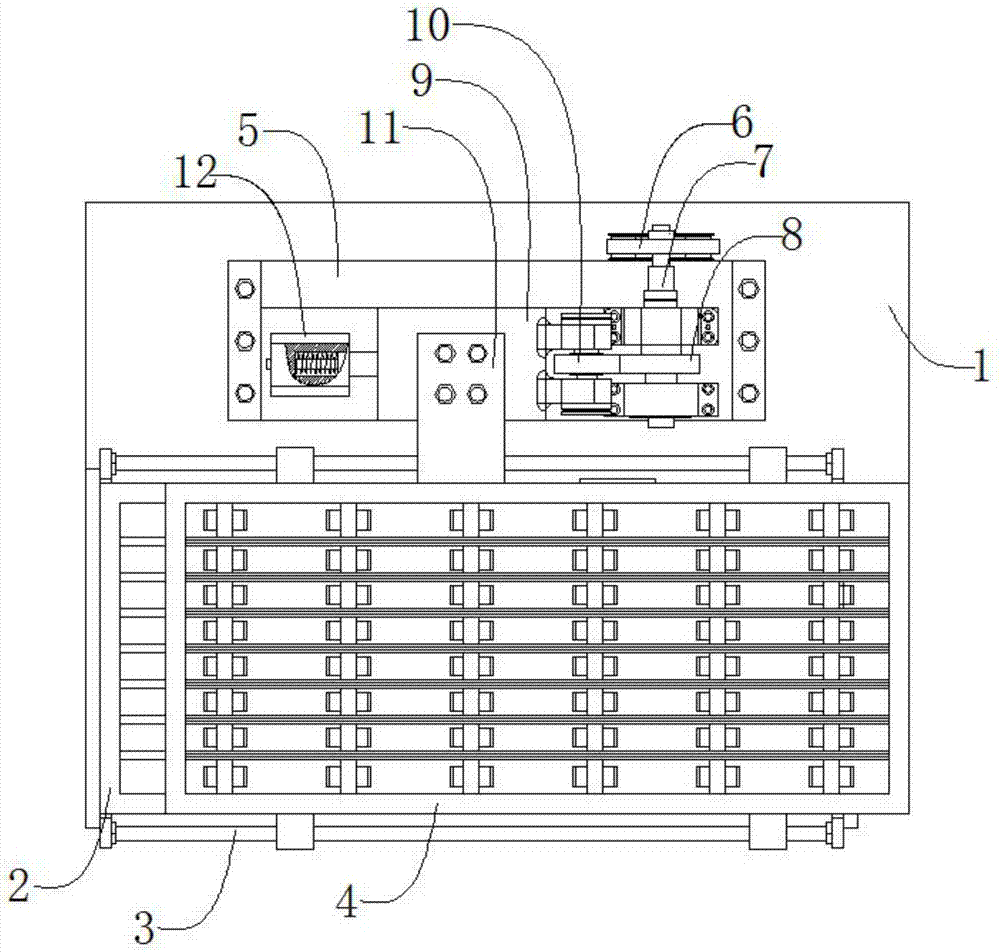
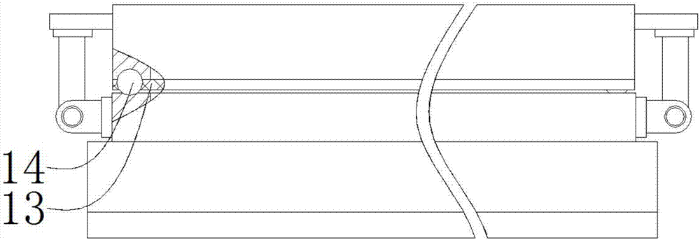
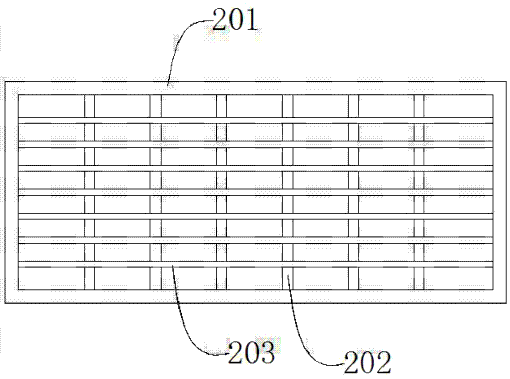
[0031] Such as figure 1 , figure 2 , image 3 , Figure 4 , Figure 5 As shown, a sludge shredding device includes a support plate 1, a lower grille 2, a guide rod 3, an upper grille 4, a bracket 5, a power mechanism 6, a rotating shaft 7, a cam 8, a sliding plate 9, and a guide wheel 10. , The connecting plate 11, the reset mechanism 12, the limit plate 13, the steel ball 14, the lower grid 2 is located at the upper end of the support plate 1, the lower grid 2 is threadedly connected with the support plate 1, the lower grid A guide rod 3 is provided on both sides of the grid 2, and the guide rod 3 is threadedly connected to the lower grid 2, and the upper grid 4 is located at the upper end of the lower grid 2 and is penetrated by the guide rod 3. The grid 4 is connected with the guide rod 3 by a gap, the bracket 5 is located at the upper end of the support plate 1, the bracket 5 is threadedly connected with the support plate 1, the power mechanism 6 is located on the right si...


PUM


Abstract

The invention discloses a sludge chopping device, which comprises a support plate, a lower grid, a guide rod, an upper grid, a bracket, a power mechanism, a rotating shaft, a cam, a slide plate, a guide wheel, a connecting plate, a reset mechanism, a position limiting When the sludge falls on the upper grid, the power mechanism drives the cam to rotate through the rotating shaft, thereby pushing the sliding plate fixedly connected with the guide wheel to slide, and then drives the upper grid to move along the guide rod. When the sliding plate moves to the left , the spring is compressed, and when the cam reaches the maximum stroke, it starts to return, and the spring returns to push the slide plate to move to the right in the return stroke, so that the upper grid can move back and forth linearly along the guide rod, and the lower grid and the horizontal and vertical blades set on the upper grid can be Under the combined action, the sludge is chopped horizontally and vertically. The structure of the device is simple, the upper grid can automatically reciprocate, and the sludge is chopped horizontally and vertically under the joint action of the upper grid and the lower grid. It not only has a high degree of automation, but also cuts the sludge evenly, continuously and quickly. .

Description

technical field [0001] The invention relates to a mechanical device, in particular to a sludge chopping device. Background technique [0002] In the existing sludge treatment technologies of urban sewage treatment plants, most of them use pressure filtration or natural drying, and the water content is very high. The treated sludge can only be temporarily solidified, and as landfill treatment, it can only be a temporary treatment plan. Can not meet the increasingly stringent environmental requirements. Therefore, sludge drying technology has emerged, that is, through heating and drying, the water content of sludge is lower than 10%, and then recycled. The sludge drying process mainly includes sludge collection, continuous feeding, drying, dehydration and For comprehensive utilization, when feeding continuously, since the sludge may contain large agglomerated sludge, if it is directly dried, it will often not be completely dried and dehydrated, which will affect the final deh...

Claims


Application Information

Patent Timeline
IPC IPC(8): B02C18/02B02C18/04
CPCB02C18/02B02C18/04B02C2201/06
Inventor 王效平
Owner 东至县文元瓷砖加工厂
Why Eureka
Try Eureka