
Novel anaerobic fermentation tank and up-flow full-mixing type anaerobic fermentation system

An anaerobic fermentation tank, a new type of technology, applied in the direction of bioreactor/fermenter combination, specific-purpose bioreactor/fermenter, biochemical equipment, etc., can solve the problems of easy stratification, difficult maintenance, and poor fluid stirring effect To achieve the effect of ensuring the fermentation temperature, convenient construction and convenient maintenance

Inactive Publication Date: 2017-12-01
南京通用电气装备有限公司
View PDF5 Cites 3 Cited by
  • Summary
  • Abstract
  • Description
  • Claims
  • Application Information

AI Technical Summary

Problems solved by technology

However, the current domestic upflow anaerobic fermentation system has the following problems: 1) The diameter is small and the height is too high, resulting in poor fluid mixing effect and easy to form stratification; 2) The spray pipe is fixed and the spray direction is fixed. Only partial mixing can be formed, and the spray pipe in the tank is easy to block and difficult to maintain; 3) Like the fully mixed anaerobic fermentation tank, in order to maintain the fermentation temperature, a heating coil is installed in the tank, which is not conducive to maintenance
[0005] Whether it is an upflow or fully mixed anaerobic fermentation system, it is necessary to set up an independent mechanical feeding device. During the fermentation process, once the feeding device fails, it will affect the operation of the entire biogas project

Method used


Image

  • Novel anaerobic fermentation tank and up-flow full-mixing type anaerobic fermentation system
  • Novel anaerobic fermentation tank and up-flow full-mixing type anaerobic fermentation system
  • Novel anaerobic fermentation tank and up-flow full-mixing type anaerobic fermentation system

Examples


Embodiment Construction

[0024] The present invention will be further illustrated below in conjunction with the accompanying drawings and specific embodiments. This embodiment is implemented on the premise of the technical solution of the present invention. It should be understood that these embodiments are only used to illustrate the present invention and are not intended to limit the scope of the present invention.

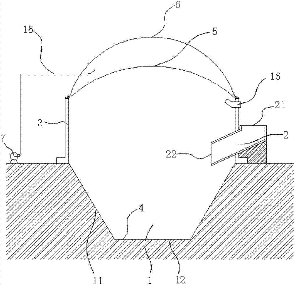
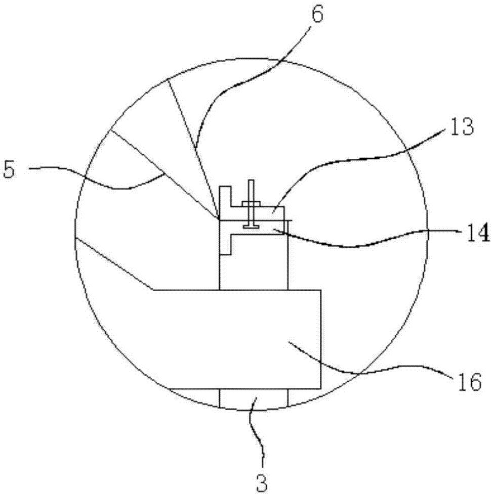
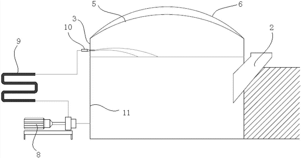
[0025] like figure 1 As shown, the embodiment of the present invention provides a novel anaerobic fermenter, which includes a base tank 1 dug out of the ground, a feed bin 2 communicated with the base tank 1, and the ground around the base tank 1 The shape of the upper tank wall 3 and the base tank 1 can be rectangular, and it is preferable to set the base tank 1 as an inverted conical or cylindrical shape. The base pool 1 includes a side wall 11 and a pool bottom 12. After the base pool 1 is dug out, the side wall 11 and the pool bottom 12 are compacted, and then a multi-layer waterpro...


PUM


Abstract

The invention discloses a novel anaerobic fermentation tank and an up-flow full-mixing type anaerobic fermentation system. The fermentation tank comprises an underground base tank, a feeding chamber and an upper tank wall. The base tank is internally provided with multiple layers of waterproof membranes, an inner gas storage membrane and an outer gas storage membrane are mounted on the upper tank wall, and an air blower is connected between the inner gas storage membrane and the outer gas storage membrane. Compared with concrete or a steel tank, the fermentation tank with the underground portion in a form of the directly coated base tank has advantages of convenience in construction and low manufacturing cost; external mechanical feeding devices are few, production halting caused by mechanical faults is avoided, and convenience in maintenance and low energy consumption are realized; by a heat exchanger, circulation biogas slurry can be heated directly by biogas power generation waste heat and then injected into the fermentation tank, so that fermentation temperature is guaranteed; multiple nozzles are in uniform arrangement and available for injection order switching to guarantee completeness in spraying and stirring; no mechanical device requiring maintenance is arranged in the tank, so that the risk of tank clearing due to faults of equipment in the tank is completely avoided.

Description

technical field [0001] The invention relates to the field, in particular to a novel anaerobic fermentation tank and an upflow fully mixed anaerobic fermentation system. Background technique [0002] Since the development of biogas anaerobic fermentation technology, after decades of practice and exploration of large and medium-sized biogas projects around the world, several technologies have been proved to be relatively successful, among which the fully mixed anaerobic process (CSTR) and upflow technology are the most widely used. UASB fermentation process. These two anaerobic fermentation methods have their own advantages and disadvantages. [0003] Fully mixed anaerobic fermentation tank, in Germany, where the development of biogas projects is the most mature in the world, this form of reactor accounts for more than 95% of the total biogas projects. Fermenters are upright cylindrical tanks, generally large in diameter and relatively small in height. The bottom foundation...

Claims


Application Information

Patent Timeline
Patent Type & Authority Applications(China)
IPC IPC(8): C12M1/00C12M1/107
CPCC12M21/04C12M23/20C12M23/36C12M29/18Y02E50/30
Inventor 孟蓬强
Owner 南京通用电气装备有限公司
Learn More