Manual control valve of harvester

A manual control and harvester technology, which is applied in the hydraulic field, can solve problems affecting control stability and accuracy, insufficient supply of hydraulic oil pressure changes, unstable oil pressure of control oil, etc., to achieve long speed regulation area and improve stability , the effect of reducing pressure loss

Active Publication Date: 2017-12-01
ZHEJIANG HAIHONG HYDRAULIC TECH
View PDF11 Cites 2 Cited by
  • Summary
  • Abstract
  • Description
  • Claims
  • Application Information

AI Technical Summary

Problems solved by technology

However, the problem with the structure of the above-mentioned control valve is that there are many oil passages in the valve body, resulting in a large pressure loss, insufficient supply of hydraulic oil or large pressure changes, resulting in unstable oil pressure of the control oil, affecting the stability and stability of the control. Accuracy
Moreover, the existing hydraulic reversing valve structure has a short speed regulating area, which is prone to high-pressure shocks. After the valve stem returns to the neutral position, the hydraulic lock returns to the position for a long time, which is not conducive to the locking of the actuator.

Method used


Image

  • Manual control valve of harvester
  • Manual control valve of harvester
  • Manual control valve of harvester

Examples


Embodiment Construction

[0035] The following are specific embodiments of the present invention and in conjunction with the accompanying drawings, the technical solutions of the present invention are further described, but the present invention is not limited to these embodiments.

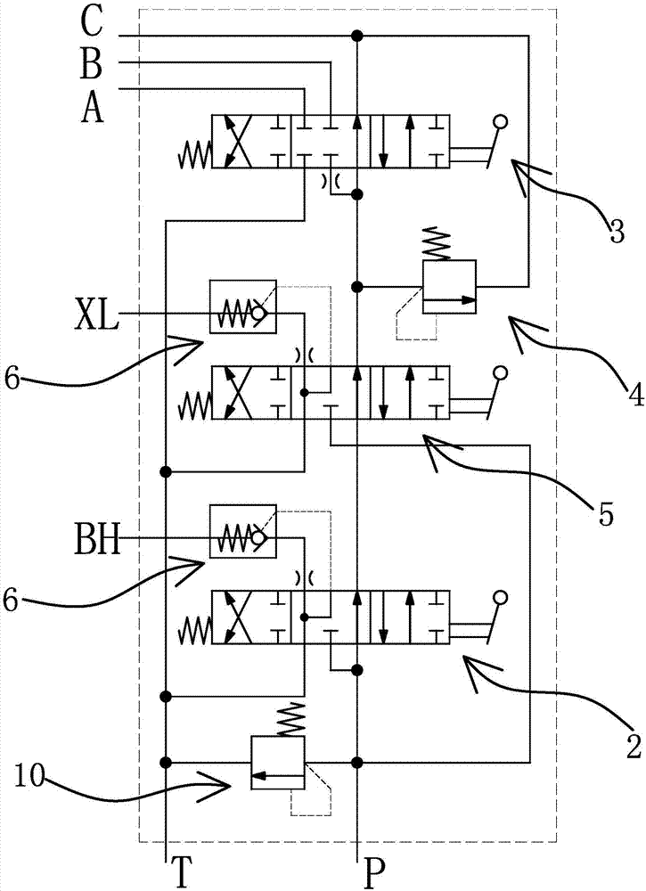
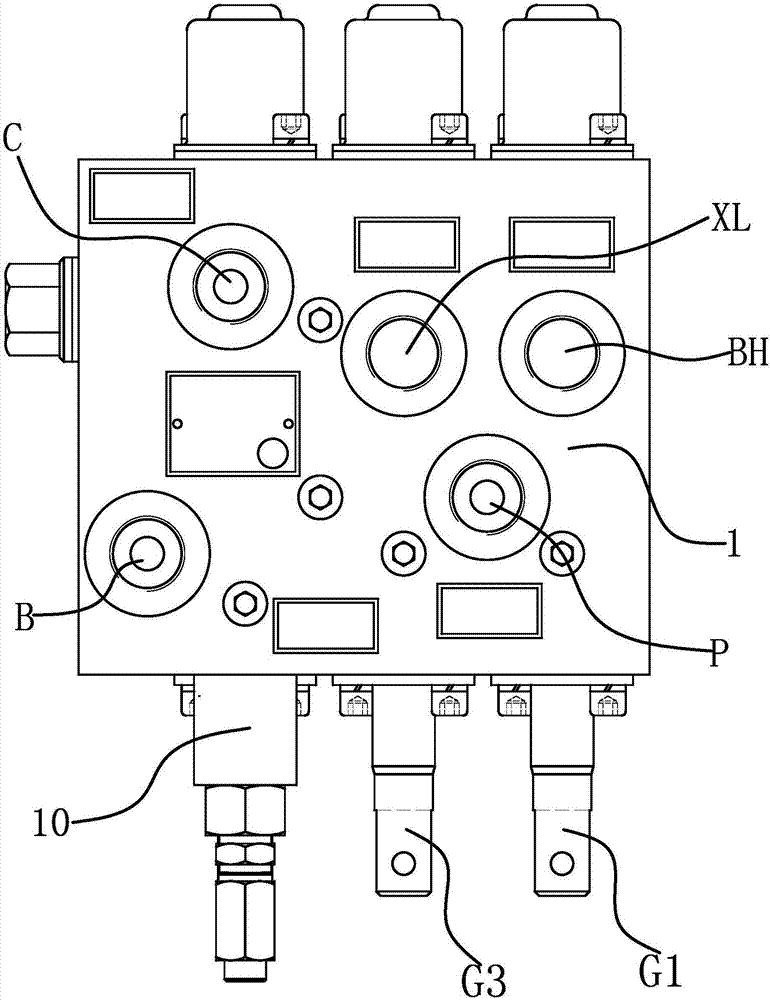
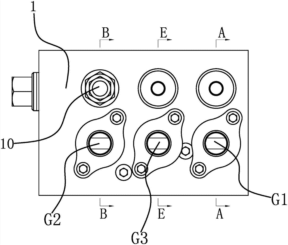
[0036] The harvester manual control valve includes valve body 1, reversing control valve 1 2, reversing control valve 2 3, oil inlet P, oil return port T, control oil port 1 BH, control oil port 2 A, control oil port Three B and transfer oil port C.

[0037] In this embodiment, the manual control valve for controlling the lifting of the reel, the lifting of the unloading barrel and the rotation of the gun barrel is taken as an example to introduce the specific implementation of the manual control valve of the harvester. Such as figure 1 As shown, the harvester manual control valve also includes a reversing control valve three 5, and the valve body 1 also has a control oil port four XL. The reversing control valve 1 2, re...


PUM


Abstract

The invention provides a manual control valve of a harvester and belongs to the technical field of hydraulic pressure. The manual control valve of the harvester solves the problem that an existing manual control valve of a harvester is poor in control stability and control accuracy degree. The manual control valve of the harvester comprises a valve body; a first reserving control valve and a second reserving control valve are connected with an oil inlet and an oil returning port in a series-parallel connection manner; a first control oil way of the first reserving control valve can be communicated with a first control oil port in the valve body; fixing throttling holes are formed in the first control oil way; a communicating oil way is further arranged on the first reserving control valve; the second reserving control valve is provided with an oil supplying oil way and an oil inflow oil way which is provided with throttling small holes; a second control oil way and a third control oil way of the second reserving control valve can be communicated with a second control oil port and a third control oil port in the valve body correspondingly; the second reserving control valve is further provided with a turning-connection oil way communicated with a turning-connection oil port in the valve body; and the oil supplying oil way and the turning-connection oil way are connected through a flow pressure control valve. The manual control valve of the harvester improves the control precision and the control stability.

Description

technical field [0001] The invention belongs to the technical field of hydraulic pressure and relates to a harvester manual control valve. Background technique [0002] The harvester is an integrated machine for harvesting crops. It completes harvesting and threshing at one time, and gathers the grains into the storage bin, and then transports the grains to the transport vehicle through the conveyor belt. For example, the current rice harvester has five main actions: reel lifting, barrel lifting, barrel rotation, header lifting and left and right steering. The hydraulic system of the rice harvester can be configured as an integrated valve for reel lifting, cannon barrel lifting and rotating, and an integrated valve for header lifting and left and right steering. [0003] An integrated valve for header lifting and left and right steering, for example, an agricultural machinery header steering valve developed and applied for by the applicant [Application No. 201520287810.X; A...

Claims


Application Information

Patent Timeline
Patent Type & Authority Applications(China)
IPC IPC(8): F15B13/02F16K11/07F16K27/04
CPCF15B13/021F16K11/0716F16K27/041
Inventor 何贤剑呼延宏陈净生高振家高利
Owner ZHEJIANG HAIHONG HYDRAULIC TECH
Why Eureka
Try Eureka