Spout swinging mechanism

A swing mechanism and nozzle technology, applied in the field of boilers, can solve the problems of wind box design constraints, limited nozzle height, shortened connecting rod life and other problems, and achieve the effects of high reliability, fewer connecting parts, and reduced force

Pending Publication Date: 2017-12-01
SHANGHAI BOILER WORKS
View PDF3 Cites 4 Cited by
  • Summary
  • Abstract
  • Description
  • Claims
  • Application Information

AI Technical Summary

Problems solved by technology

[0004] 1. For nozzles with a small height, there is a problem of collision between the connecting rod and the nozzle, which requires opening a gap at the collision position of the nozzle to avoid the connecting rod, which reduces the strength of the nozzle;
[0005] 2. When the nozzle swings, in a certain direction, the connecting rod will approach the furnace and enter a high temperature environment, which will easily reduce the life of the connecting rod;
[0006] 3. Restricted by the radius of rotation of the connection point on the spout, the height of the spout is limited to a certain minimum value, which restricts the design of the bellows accordingly

Method used


Image

  • Spout swinging mechanism
  • Spout swinging mechanism
  • Spout swinging mechanism

Examples


Embodiment 1

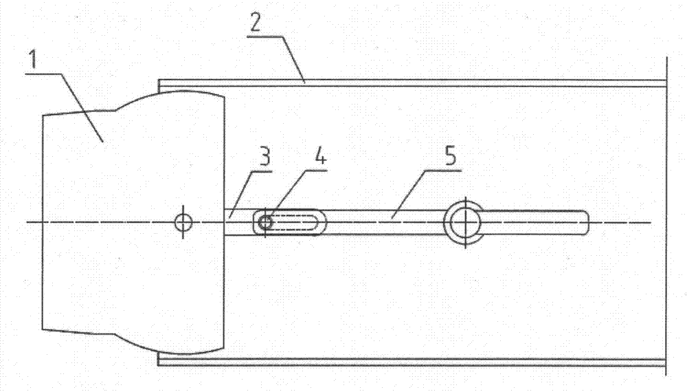
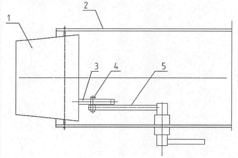
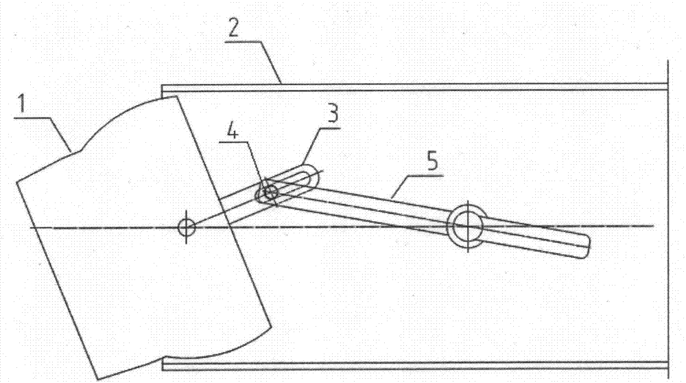
[0033] Figure 1 ~ Figure 3 This is a schematic diagram of the nozzle swing mechanism shown in this embodiment. The nozzle swing mechanism is composed of the nozzle 1, the wind box 2, the swing arm 3, the pin sleeve 4, the main rocker 5 and the like.

[0034] The spout 1 is fixed on the wind box 2 by its own central rotating shaft, and can rotate around the central rotating shaft.

[0035] One end of the swing arm 3 is fixedly connected to the spout 1, and the other end has a waist-shaped hole. The position of the swing arm 3 fixed on the nozzle 1 can be adjusted.

[0036] The main rocker 5 is Z-shaped and is composed of an inner connecting rod, a main connecting rod and an outer connecting rod connected in sequence. The main link is fixed on the bellows 2 and can rotate around the fixed center; the inner link is located inside the bellows 2, one end of the inner link is connected to one end of the main link, and the other end of the inner link has a round hole; the outer link is lo...

Embodiment 2

[0042] Figure 4 ~ Figure 6 This is a schematic diagram of the nozzle swing mechanism shown in this embodiment. The nozzle swing mechanism is composed of the nozzle 1, the wind box 2, the swing arm 3, the pin sleeve 4, the main rocker 5, the transition lever 6, and the like.

[0043] The spout 1 is fixed on the wind box 2 by its own central rotating shaft, and can rotate around the central rotating shaft.

[0044] One end of the swing arm 3 is fixedly connected to the spout 1, and the other end has a waist-shaped hole. The position of the swing arm 3 fixed on the nozzle 1 can be adjusted.

[0045] The main rocker 5 is Z-shaped and is composed of an inner connecting rod, a main connecting rod and an outer connecting rod connected in sequence. The main link is fixed on the bellows 2 and can rotate around the fixed center; the inner link is located inside the bellows 2, one end of the inner link is connected to one end of the main link, and the other end of the inner link has a waist ...


PUM


Abstract

The invention provides a spout swinging mechanism. The spout swinging mechanism comprises a bellows, and a spout is arranged on the bellows through a central rotating shaft of the spout and can rotate around the central rotating shaft; one end of a swinging arm is fixed to the spout, and the other end of the swinging arm is provided with a kidney-shaped hole; a main rocker is composed of an inner connecting rod, a main connecting rod and an outer connecting rod which are sequentially connected in a Z shape; the main connecting rod is fixed to the bellows and can rotate around a fixed center, the inner connecting rod is arranged in the bellows, and the outer connecting rod is arranged on the outer side of the bellows; and the inner connecting rod is connected with the kidney-shaped hole at the other end of the swinging arm through a connecting device in a free rotating mode. According to the spout swinging mechanism, the swinging arm of the spout is located on the rear side of the spout and far away from a high temperature radiation area of a hearth, the service life is long, and jamming is not likely to occur; the transmission structure is simple, connecting parts are few, reliability is high, and manufacturing, processing and installing are easy; arm of force of swinging of the spout is long, the imposed acting force can be reduced significantly, and the labor-saving effect is achieved; and the spout is not affected by the swinging arm, the spout intensity and height are not reduced, and design of the bellows is not affected accordingly.

Description

Technical field [0001] The invention relates to a nozzle swing mechanism and belongs to the technical field of boilers. Background technique [0002] In the actual operation of the boiler, due to the needs of boiler load changes, combustion conditions adjustment, pollutant emission control, prevention of coking, high temperature corrosion of water walls, etc., the burner nozzle needs to have a swing function to make the primary and secondary The direction of the air flow can be adjusted in a timely manner, which is convenient for adjusting the height of the furnace flame center and adjusting the deviation of the flue gas temperature. [0003] The swing of the nozzle of the traditional boiler burner mostly adopts a planar linkage mechanism, and the swing is realized by a quadrilateral swing. There are some inherent shortcomings in this approach: [0004] 1. For nozzles with a small height, there is a problem of collision between the connecting rod and the nozzle, which requires open...

Claims


Application Information

Patent Timeline
Patent Type & Authority Applications(China)
IPC IPC(8): F23C7/00F23L1/00F23L9/00
CPCF23C7/00F23L1/00F23L9/00
Inventor 李鹏翔李江涛黄芳
Owner SHANGHAI BOILER WORKS
Why Eureka
Try Eureka