Hybrid signal source locating method and hybrid signal source locating system

A mixed-signal, source positioning technology, applied in positioning, radio wave measurement systems, measurement devices, etc., can solve the problems of unconsidered array phase ambiguity, array error, large computational complexity, etc., to shorten the positioning operation time, reduce The effect of computational complexity

Inactive Publication Date: 2017-12-01
HUIZHOU UNIV
View PDF9 Cites 9 Cited by
  • Summary
  • Abstract
  • Description
  • Claims
  • Application Information

AI Technical Summary

Problems solved by technology

Moreover, the existing research on near-field incident sources is basically based on the assumption that the array is ideal (that is, the ideal array model); however, with the expansion of the practical application range, the incident signals are complex and diverse, and the Mixed signals of field signal sources are more common. At the same time, due to factors such as ambient humidity and temperature changes, array vibration, and aging of active devices, inevitable array errors will be caused, so that the actual array flow pattern is often Will deviate from the ideal array model, there is a certain degree of disturbance or deviation
[0023] All in all, there are many defects in the existing source location technology solutions, including: near-field source location methods usually require multi-dimensional search and calculation of multiple high-order cumulant matrices, and two-dimensional parameter matching is required, so the computational complexity Large, long calculation time; not suitable for mixed signal source positioning where near-field and far-field signal sources exist simultaneously; there is array error; phase ambiguity of array phase response estimation is not considered
At this time, the positioning performance of the system will seriously deteriorate, or even fail, which greatly limits its application.

Method used


Image

  • Hybrid signal source locating method and hybrid signal source locating system
  • Hybrid signal source locating method and hybrid signal source locating system
  • Hybrid signal source locating method and hybrid signal source locating system

Examples


Embodiment 1

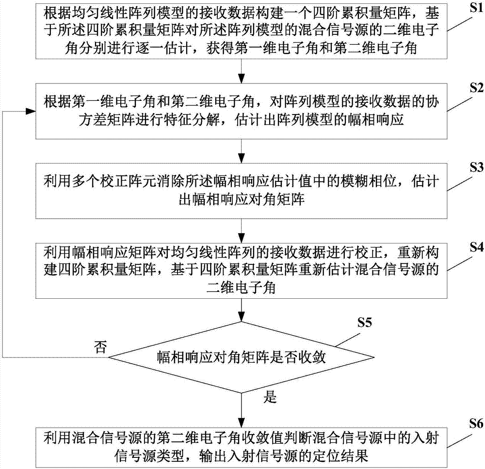
[0086] See image 3 , Is a flowchart of the steps of an embodiment of the method for locating a mixed signal source provided by the present invention.

[0087] In this embodiment, the mixed signal source positioning method mainly includes the following steps S1 to S6:

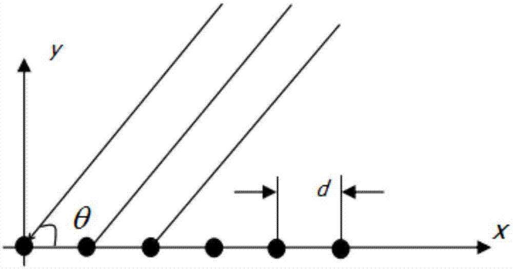
[0088] Step S1: According to the uniform linear array model (such as figure 2 The received data shown in) constructs a fourth-order cumulant matrix. Based on the fourth-order cumulant matrix, the two-dimensional electronic angles of the mixed signal source of the array model are respectively estimated one by one to obtain the first-dimensional electronic angle ω and the first Two-dimensional electronic angle Specifically, by constructing a special fourth-order cumulant matrix that contains only one-dimensional estimation parameters, the dimension of the parameters can be effectively reduced, thereby reducing the computational complexity and shortening the positioning running time.

[0089] In order to obtain a more ...

Embodiment 2

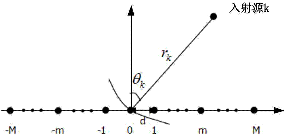
[0232] In order to make the objectives, technical solutions, and advantages of the present invention clearer, the following describes the embodiments of the present invention in further detail in combination with a uniform linear array composed of 2M+1=11 array elements (ie, M=5).

[0233] See Figure 4 , Is a schematic diagram of the composition of an embodiment of the uniform linear array model provided by the present invention.

[0234] in Figure 4 In the embodiment, the uniform linear array includes 2M+1=11 equidistant array elements, and two of the array elements are set as the required correction elements ( Figure 4 In the correction array element of the embodiment, the array elements labeled 5 and -5 are preferably correction array elements).

[0235] See Figure 5 , Is a flowchart of the steps of another embodiment of the method for positioning a mixed signal source provided by the present invention.

[0236] Specifically, based on Figure 4 The provided array model, this emb...

Embodiment 3

[0258] See Image 6 Is a schematic structural diagram of an embodiment of the mixed signal source positioning system provided by the present invention.

[0259] The mixed signal source positioning system provided in this embodiment includes:

[0260] The mixed signal source parameter estimation module 100 is configured to construct a fourth-order cumulant matrix based on the received data of the uniform linear array model, and perform the two-dimensional electronic angle of the mixed signal source of the array model on the basis of the fourth-order cumulant matrix. Estimate one by one, obtain the first-dimensional electronic angle and the second-dimensional electronic angle, and obtain the first-dimensional electronic angle ω and the second-dimensional electronic angle

[0261] The array amplitude and phase response estimation module 200 is used to calculate the first-dimensional electronic angle ω and the second-dimensional electronic angle Perform eigen decomposition on the covar...


PUM


Abstract

A hybrid signal source locating method includes: constructing a fourth-order cumulant matrix according to the received data of a uniform linear array model; estimating the two-dimensional electronic angles of the hybrid signal source one by one; performing eigen-decomposition on the covariance matrix of the received data of the uniform linear array model to estimate the amplitude-phase response of the array model; using a plurality of calibration elements to eliminate the blurring phase in the amplitude-phase response; performing iterative operation on the three processes of the two-dimensional electronic angle estimation, the amplitude-phase response estimation, and the blurring phase elimination until the convergence; obtaining the convergence values of the amplitude-phase response diagonal matrix and the two-dimensional electronic angles; determining the type of the incident signal source; and outputting an incident signal source locating result. The present invention also provides a hybrid signal source positioning system. The implementation of the technical schemes provided by the invention can effectively reduce the computational complexity and shorten the operation time for locating, and meanwhile locates the hybrid signal source of the near field and the far field, improving the locating accuracy and the application range.

Description

Technical field [0001] The invention relates to the technical field of signal source positioning, in particular to a mixed signal source positioning method and a mixed signal source positioning system. Background technique [0002] Signal source positioning technology can be simply understood as determining the direction and location of the required useful signals, and it is widely used in communications, radio astronomy, seismic prospecting, radar, medicine and other fields. The current signal source positioning technology can be divided into far-field source positioning and near-field source positioning according to the distance of the signal source from the receiving array. [0003] For the far-field signal source, the incoming wave signal of the receiving array is in the form of a plane wave, and its direction of arrival (DOA) determines the position of the source at this time, such as figure 1 As shown, when locating the far-field signal source, the incident angle θ needs to b...

Claims


Application Information

Patent Timeline
Patent Type & Authority Applications(China)
IPC IPC(8): G01S5/04
CPCG01S5/04
Inventor 崔晗刘佟彭文娟汪茂稳
Owner HUIZHOU UNIV
Why Eureka
Try Eureka