
Cooling air channel structure of dry type transformer

A technology of dry-type transformer and cooling air duct, which is applied in transformer/inductor cooling, transformer/inductor parts, transformer/reactor installation/support/suspension, etc. Hot air cannot be discharged in time, energy is not fully utilized, etc., to improve the cooling effect, prevent pipe blockage, and improve cooling efficiency

Active Publication Date: 2017-12-01
山东新碧园生态园林有限公司
View PDF9 Cites 4 Cited by
  • Summary
  • Abstract
  • Description
  • Claims
  • Application Information

AI Technical Summary

Problems solved by technology

But dare to mess with the transformer. During the use process, the transformer coil will emit a lot of heat due to the excessive current. If it cannot be dissipated in time, it will seriously affect the performance of the transformer and even cause danger. The existing transformer cooling air duct has the following problems:
[0004] (1) The cooling air duct structure is too simple, the cold air circulation is limited, the hot air cannot be discharged in time, and the ideal heat dissipation effect cannot be achieved well;
[0005] (2) Most of the cooled exhaust gas is directly discharged, which not only makes insufficient use of energy, but also pollutes the air

Method used


Image

  • Cooling air channel structure of dry type transformer
  • Cooling air channel structure of dry type transformer
  • Cooling air channel structure of dry type transformer

Examples


Embodiment

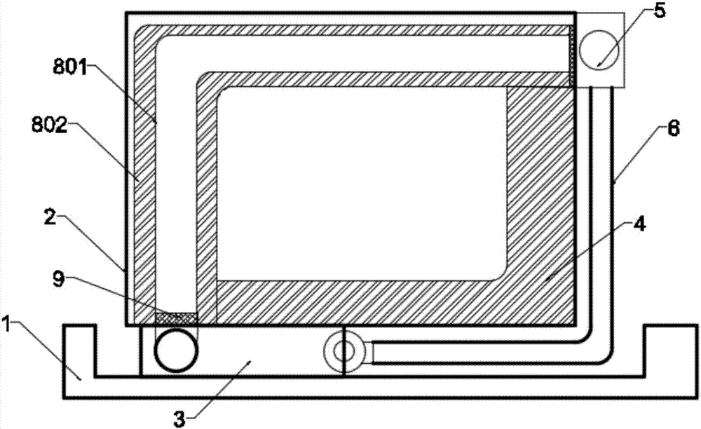
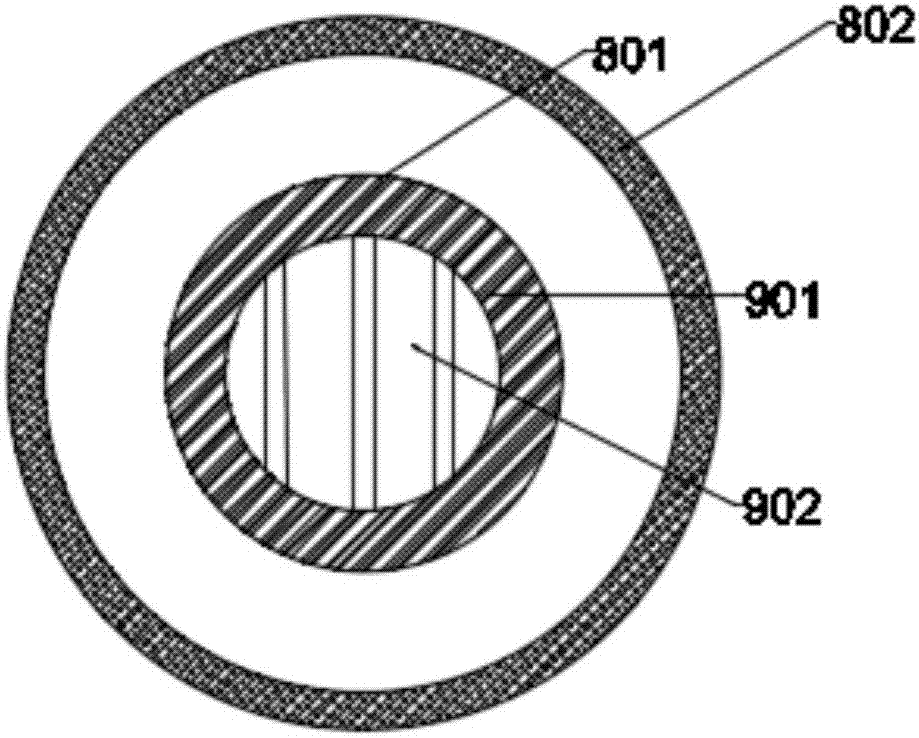
[0029] Such as figure 1 and figure 2 As shown, the present invention provides a dry-type transformer cooling duct structure, including a fixed base 1, a fixed groove is dug in the center of the upper surface of the fixed base 1, and a transformer box 2 is embedded in the groove. There are circular through holes dug on the bottom of both sides of the box body 2, and there is a cooling fan 3 temporarily under the circular through holes; the fixed base 1 and the transformer box body 2 are both made of insulating materials, have good insulation performance, and are fixed There are threaded mounting holes drilled on the base 1, which can be easily installed and disassembled;

[0030] The base of the cooling fan 3 is installed on both sides of the fixed base 1 through fixing screws, and the air outlet of the cooling fan 3 is sleeved with a cooling air duct 4, and the cooling air duct 4 is connected inside the transformer box 2, and the two sides The air outlets of the side coolin...


PUM


Abstract

The invention discloses a cooling air channel structure of a dry type transformer. The cooling air channel structure comprises a fixed base; a transformer box is embedded on the upper surface of the fixed base; circular through holes are formed in the bottoms on the two sides of the transformer box; a cooling fan is embedded below the circular through holes; the air outlet of the cooling fan is sleeved with a cooling air channel; the cooling air channel passes through the interior of the transformer box, and the air outlets of the cooling air channel on the two sides are both provided with air pumps; the air pumps are fixed on the top surface of the shell of the transformer box; the air outlets of the air pumps are connected with backflow cooling pipes; the tail ends of the backflow cooling pipes are connected to the coolant inlet of the cooling fan through a three-way valve; the cooling air channel comprises an air channel pipe; an air division plate is mounted in the air inlet of the air channel pipe; and a filtering net is embedded in the outlet of the air channel pipe. By adoption of the cooling air channel structure, shunting of cold air and hot air is realized, the cooling effect can be improved, and recycling can be realized to save energy and reduce pollution.

Description

technical field [0001] The invention relates to the field of transformer equipment, in particular to a dry-type transformer cooling air channel structure. Background technique [0002] A transformer is a device that transforms AC voltage, current, and impedance. When an AC current passes through the primary coil, an AC magnetic flux is generated in the iron core (or magnetic core), which induces a voltage (or current) in the secondary coil. The transformer consists of an iron core (or magnetic core) and a coil. The coil has two or more windings. The winding connected to the power supply is called the primary coil, and the remaining windings are called the secondary coil. In a generator, whether the coil moves through the magnetic field or the magnetic field moves through the fixed coil, an electric potential can be induced in the coil. In both cases, the value of the magnetic flux remains the same, but the amount of magnetic flux intersecting the coil is different. Change, ...

Claims


Application Information

Patent Timeline
Patent Type & Authority Applications(China)
IPC IPC(8): H01F27/06H01F27/08
CPCH01F27/06H01F27/085
Inventor 陈波
Owner 山东新碧园生态园林有限公司
Learn More