Eureka AIR delivers breakthrough ideas for toughest innovation challenges, trusted by R&D personnel around the world.

Pin welding device and method

A pin and soldering process technology, which is applied in the field of soldering pin devices, can solve problems such as easy oxidation of the soldering point, inability to complete soldering, and long heating time, and achieve the effects of fast speed, easy operation, and high thermal efficiency

Inactive Publication Date: 2017-12-08
邓娴
View PDF7 Cites 0 Cited by
  • Summary
  • Abstract
  • Description
  • Claims
  • Application Information

AI Technical Summary

Problems solved by technology

[0003] In the existing technology, all welding methods will cause the temperature of each electronic component to be different at a certain point in time. The temperature that rises quickly may have formed a solder joint, while the temperature that rises slowly has not yet reached the temperature required for the formation of a solder joint. The required temperature, if an electronic part is so large that it cannot rise to the temperature required for welding for a long time, its surface will be oxidized by air, and eventually the welding cannot be completed, so for multiple pins, flat The structure with large pins and pads and many winding stacks needs to absorb a lot of heat when it reaches the welding temperature, and it takes a long time to be heated, which will easily cause the spots to be welded to be easily oxidized and the welding cannot be completed

Method used


Image

  • Pin welding device and method
  • Pin welding device and method

Examples


Embodiment Construction

[0024] The technical solution of the present invention is further described below, but the scope of protection is not limited to the description.

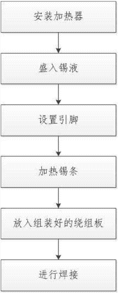
[0025] like figure 1 As shown, a method of soldering pins, in the welding process, put the winding plate with the pins into the device filled with tin liquid, and the lead wire will be controlled by the heater, buzzer, timer and PID controller. The feet and the winding plate are soldered.

[0026] Based on a device and method for soldering pins, comprising the following steps:

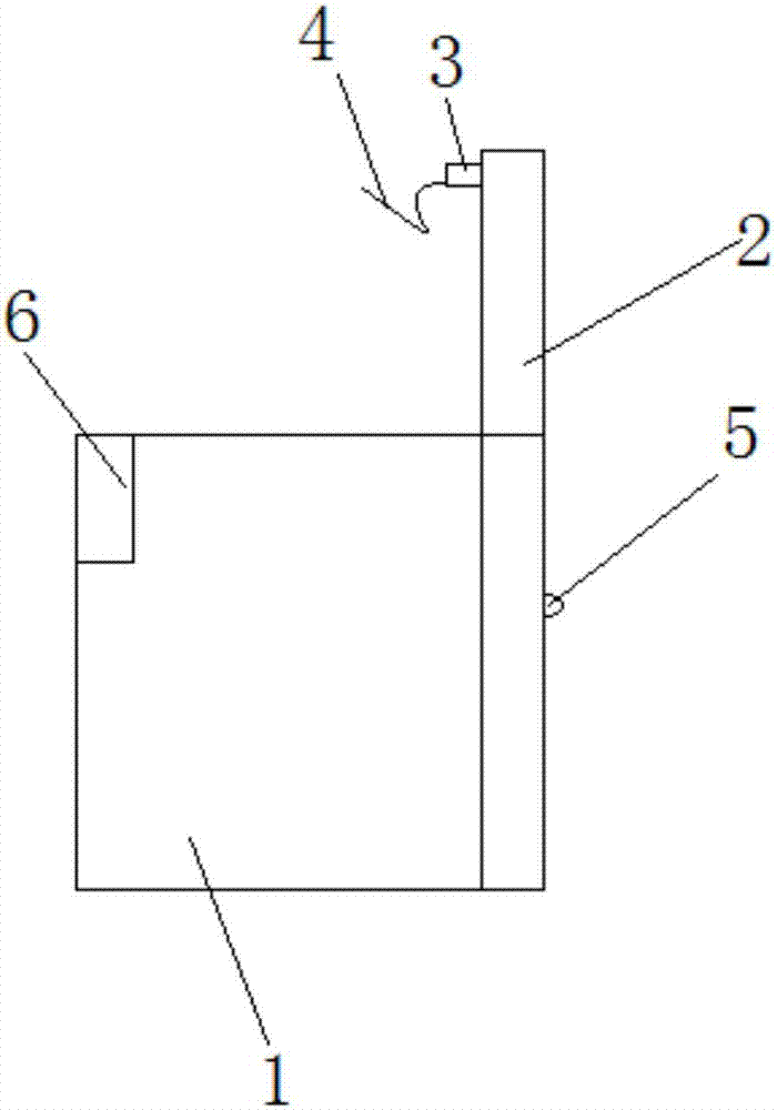
[0027] ①Install the heater and PID controller: put the heater at the bottom of the device to make it heat faster and heat transfer evenly, install the PID controller, buzzer and timer on one side, and connect the heater, buzzer buzzer, timer and PID controller, and then weld the heater, buzzer, timer and PID controller to the device;

[0028] ②Put tin liquid: Put the tin bar into the device, the solid is easy to operate and will not be poured as easily a...


PUM


Abstract

The invention provides a pin welding device and method. In a welding process, a winding plate where a pin penetrates is placed into a device containing tin liquid, and the pin and the winding plate are welded through a heater, a buzzer, a timer and a PID controller. The purpose that the pin and the winding plate are welded is achieved by means of the PID controller and a heating plate, accordingly, the heating temperature is constant, the heating area is uniform, the speed is high, the heat efficiency is high, and operation is convenient.

Description

technical field [0001] The invention relates to a device and method for welding pins, belonging to the technical field of transformer pin welding. Background technique [0002] In all electronic products, the metal leads or electrical connection points of electronic parts must be connected by tin soldering. Commonly used soldering methods include hot air reflow soldering, wave soldering, and soldering iron soldering. When soldering, the heat source heats the electronic parts, so that the temperature of the point to be soldered exceeds the melting point of the solder material by 20 to 50 degrees, and maintains it for a certain period of time. The solder material melts into a liquid state and surrounds the point to be soldered. After cooling, a solder is formed. point, thus completing the fixing of electronic parts and electrical communication. [0003] In the existing technology, all welding methods will cause the temperature of each electronic component to be different at a...

Claims


Application Information

Patent Timeline
Patent Type & Authority Applications(China)
IPC IPC(8): B23K3/00B23K3/08
CPCB23K3/00B23K3/08
Inventor 邓娴
Owner 邓娴
Why Eureka
Eureka Blog
Learn More