Assembly machine for draining pump valve body

A technology of assembly machine and drainage pump, which is applied in the direction of assembly machine, metal processing equipment, manufacturing tools, etc., can solve the problems of small installation space, easy deformation, difficult sealing ring, etc., to improve assembly efficiency and success rate, and improve labor health. Condition, the effect of avoiding hand contact with grease

Inactive Publication Date: 2017-12-08
JIANGMEN HUILANG IND ROBOT CO LTD
View PDF12 Cites 9 Cited by
  • Summary
  • Abstract
  • Description
  • Claims
  • Application Information

AI Technical Summary

Problems solved by technology

[0003] 1. The sealing ring is not evenly stretched manually. It is necessary to cover one side and then cover the other side. The sealing ring is easy to come out, so the installation takes a long time, the efficiency is low, and the failure rate is high;
[0004] 2. To open the sealing ring requires a lot of manual force, and long-term operation will easily cause hand fatigue and even finger injury;
[0005] 3. After the sealing ring is installed, it needs to be filled with oil around it. Oil filling will lead to increased man-hours, grease pollution, and reduced friction, which will affect the subsequent opening of the sealing ring, etc.
[0006] Considering the small installation space of the product, the fact that there is no groove in the installation position of the sealing ring, it is difficult to clamp the sealing ring, and the sealing ring is elastic, easy to deform, and more difficult to operate after oiling, etc., there is currently no relevant automation equipment to replace it. Manually realize the automatic assembly of the sealing ring

Method used


Image

  • Assembly machine for draining pump valve body
  • Assembly machine for draining pump valve body
  • Assembly machine for draining pump valve body

Examples


Embodiment Construction

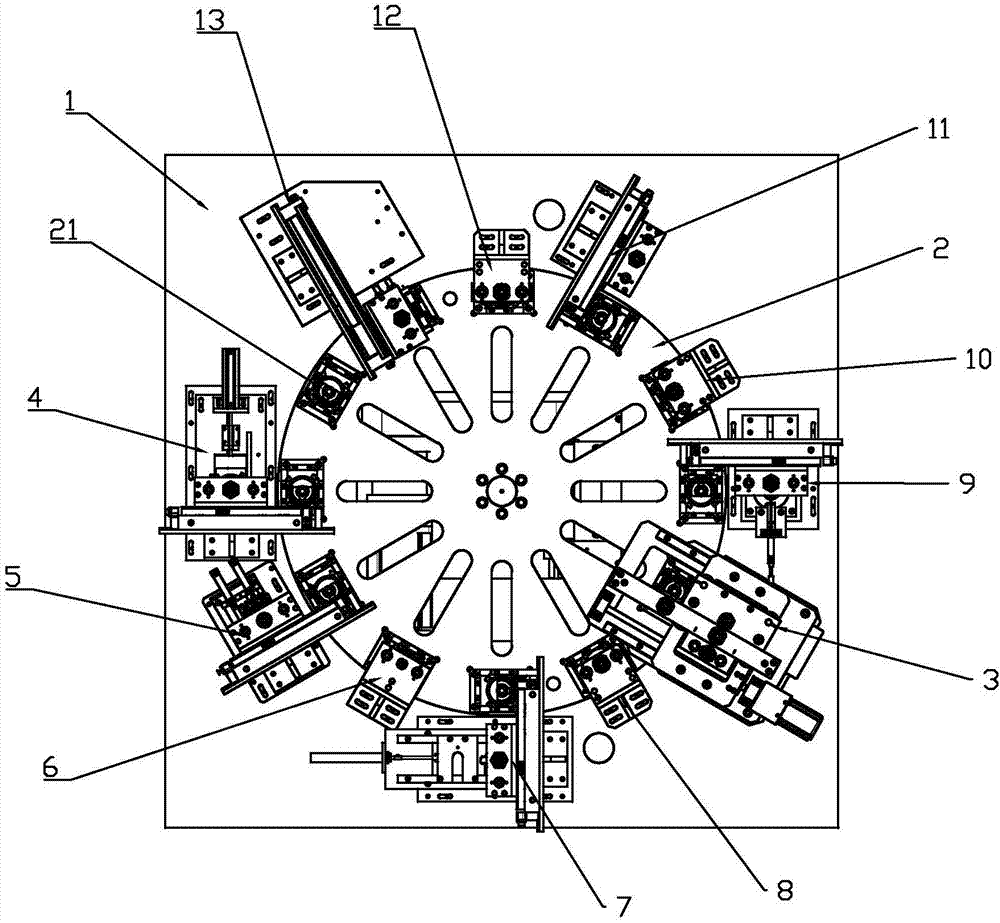
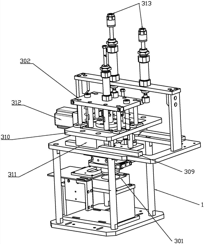
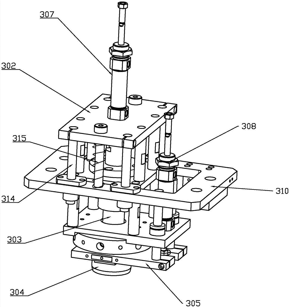
[0026] refer to Figures 1 to 4 , a drainage pump valve body assembling machine of the present invention includes a disk divider 2 installed on the frame 1, and a mounting table 21 evenly distributed on the disk divider 2, and also includes a The sealing ring installation station 3 on the outside of the disk divider 2, the sealing ring installation station 3 includes a sealing ring preset disk 301 arranged on the frame 1, located on the sealing ring preset disk The floating frame 302 above 301, the stretching mechanism and the scraping mechanism arranged on the floating frame 302, the first movement mechanism that drives the floating frame 302 to move radially along the disk divider 2, drives the The second movement mechanism for the floating frame 302 to move downward; the expansion mechanism includes a mandrel 303 with an outer tapered surface 3031 at the bottom, and a third drive component that drives the mandrel 303 to move up and down, and is arranged on the core The exp...


PUM


Abstract

The invention discloses an assembly machine for a draining pump valve body, which comprises a disc cutter, a mounting platform, and a sealing ring mounting station; the sealing ring mounting station comprises a sealing ring presetting plate, a floating frame, an opening mechanism, a scraping mechanism, a first moving mechanism and a second moving mechanism; the opening mechanism comprises a central spindle provided with an external conical surface at the bottom, a third driving part driving the central spindle to move up and down, and an opening strut arranged below the central spindle; a center hole is formed in the top of the opening strut, and an internal conical surface is formed in the center hole; the opening strut is divided into a plurality of sections in the manner of central symmetry; the scraping mechanism comprises a scraping plate and a fourth driving part driving the scraping plate to move up and down. The assembly machine can automatically finish mounting of a sealing ring in a valve body assembly, do not need manual participation in a mounting process, effectively avoid fatigue damage to hands of workers, prevent grease pollution and corrosion to skin of the hands of workers, and improve the working health conditions of the workers; meanwhile, the assembly efficiency and the success rate are greatly improved, and the reduction of production cost is facilitated.

Description

technical field [0001] The invention relates to drainage pump assembly equipment, in particular to a drainage pump valve body assembly machine. Background technique [0002] The valve body of the drainage pump for small household appliances needs to be installed with a sealing ring during the assembly process, and the sealing ring needs to be opened for installation, and the installation space is narrow. At the same time, since the valve body mouth is open, the sealing ring is easy to slide out after installation ;In the past, installing the seal ring on the valve body was usually assembled manually, but there were the following problems in the manual assembly: [0003] 1. The sealing ring is not evenly stretched manually. It is necessary to cover one side and then cover the other side. The sealing ring is easy to come out, so the installation takes a long time, the efficiency is low, and the failure rate is high; [0004] 2. Stretching the sealing ring requires a lot of fo...

Claims


Application Information

Patent Timeline
Patent Type & Authority Applications(China)
IPC IPC(8): B23P21/00
CPCB23P21/006
Inventor 周志强喻剑波
Owner JIANGMEN HUILANG IND ROBOT CO LTD
Why Eureka
Try Eureka