Identification and compensation method of industrial robot structure parameter bias

A technology of industrial robots and structural parameters, applied in manipulators, manufacturing tools, program-controlled manipulators, etc., can solve problems such as DH parameter errors, and achieve the effect of high positioning accuracy

Active Publication Date: 2017-12-08
TSINGHUA UNIV
View PDF4 Cites 43 Cited by
  • Summary
  • Abstract
  • Description
  • Claims
  • Application Information

AI Technical Summary

Problems solved by technology

In this case, if all the DH parameter errors are identified through calibration, but only a part of them is compensated, th

Method used


Image

  • Identification and compensation method of industrial robot structure parameter bias
  • Identification and compensation method of industrial robot structure parameter bias
  • Identification and compensation method of industrial robot structure parameter bias

Examples


Embodiment 1

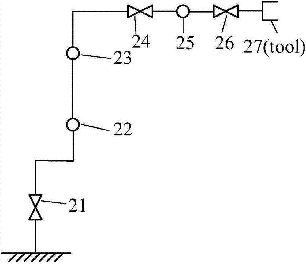
[0040] A method for identifying and compensating structural parameter errors of an industrial robot in an embodiment of the present invention can identify structural parameter errors step by step. Each joint of the industrial robot is a rotating joint or a moving joint. In this embodiment, it is set as figure 2 The six degrees of freedom industrial robot shown has six revolute joints and one manipulation tool. like figure 2 As shown, the rotation axes of the rotation joint 21, the rotation joint 24 and the rotation joint 26 are in the plane and pass through the common vertices of the two triangles. direction perpendicular to the plane.

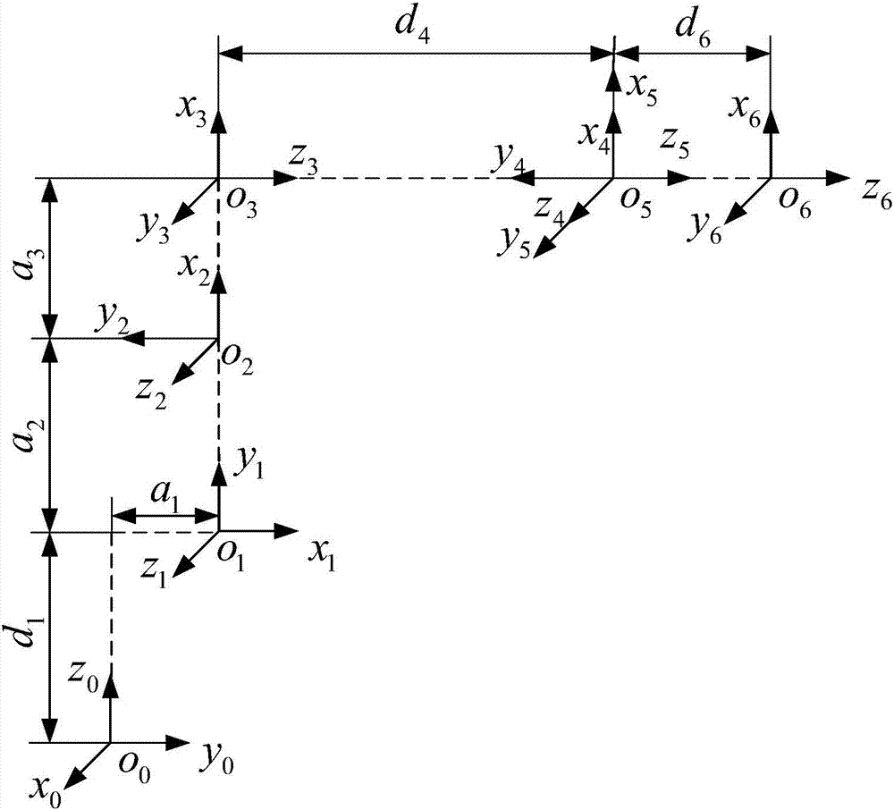
[0041] like image 3 As shown, establish the i-1 link coordinate system at the i-th joint of the industrial robot, and establish z along the direction of the rotation axis i-1 The shaft is fixedly connected with the connecting rod. x of the coordinate system of the i-th link i The direction of the axis must be perpendicular to z at the ...

Embodiment 2

[0077] A method for identifying and compensating structural parameter errors of an industrial robot in an embodiment of the present invention can simultaneously identify structural parameter errors. Each joint of the industrial robot is a rotating joint or a moving joint. In this embodiment, it is set as figure 2 The six degrees of freedom industrial robot shown has six revolute joints and one manipulation tool. In the state shown in the figure, the rotating shafts of the rotating joint 21, the rotating joint 24 and the rotating joint 26 are in the plane and pass through the common vertices of the two triangles, and the rotating axes respectively bisect the two triangles, and the rotating joint 22, the rotating joint 23 and the rotating joint The axis of rotation of 25 is in the direction perpendicular to the plane.

[0078] like image 3 As shown, establish the i-1 link coordinate system at the i-th joint of the industrial robot, and establish z along the direction of the r...


PUM


Abstract

The invention discloses an identification and compensation method of an industrial robot structure parameter bias, which includes steps of confirming compensable structure parameter bias according to a numerical control system of an industrial robot; setting up a bias model on the basis of a DH method, compulsorily zeroing the non-compensable structure parameter bias in a bias model, and then structuring a bias identification equation; selecting an identification pose, and controlling the industrial robot to move according to the identification pose; recording a joint turning angle and the terminal position data of the industrial robot; calculating the bias identification equation according to the a joint turning angle and the terminal position data, and solving the bias identification equation to obtain the structure parameter bias; modifying a corresponding structure parameter in the numerical control system of the industrial robot according to the structure parameter bias so as to compensate the structure parameter bias. The identification and compensation method has the advantages of identifying and compensating the reduction ratio bias, coupling parameter bias and DH parameter bias of the industrial robot, and reaching higher positioning precision in compensation of the bias.

Description

technical field [0001] The invention relates to the technical field of industrial robots, in particular to a method for identifying and compensating structural parameter errors of industrial robots. Background technique [0002] With the development of disciplines such as mechanical manufacturing, electronic engineering, and automatic control, the research on industrial robot technology continues to deepen. At present, industrial robots have played a role in many industries such as aerospace, machinery manufacturing, biomedicine, and food packaging, and are widely used in welding, handling, spraying, and assembly. In some emerging fields, such as fully automated factories, human-machine collaboration, robots and machine tools to achieve fully automatic processing systems, etc., industrial robots also play an important role in promoting social and economic development. [0003] Teaching is an important working method of industrial robots. By controlling industrial robots to ...

Claims


Application Information

Patent Timeline
IPC IPC(8): B25J9/16
CPCB25J9/1605B25J9/1607B25J9/1638B25J9/1653
Inventor 谢福贵刘辛军梅斌
Owner TSINGHUA UNIV
Why Eureka
Try Eureka