Waste water concentration device
A waste water concentration and waste water technology, applied in water/sewage treatment, heating water/sewage treatment, water/sludge/sewage treatment, etc., can solve the problem of limiting the amount of evaporation and concentration of waste water in spray towers, increasing the impact of flue gas on waste water Carrying, large amount of flue gas and other problems, to achieve the effect of improving heat transfer evaporation efficiency, improving utilization rate and evaporation concentration efficiency, and uniform flue gas flow field
- Summary
- Abstract
- Description
- Claims
- Application Information
AI Technical Summary
Problems solved by technology
Method used
Image

Examples
Embodiment 1
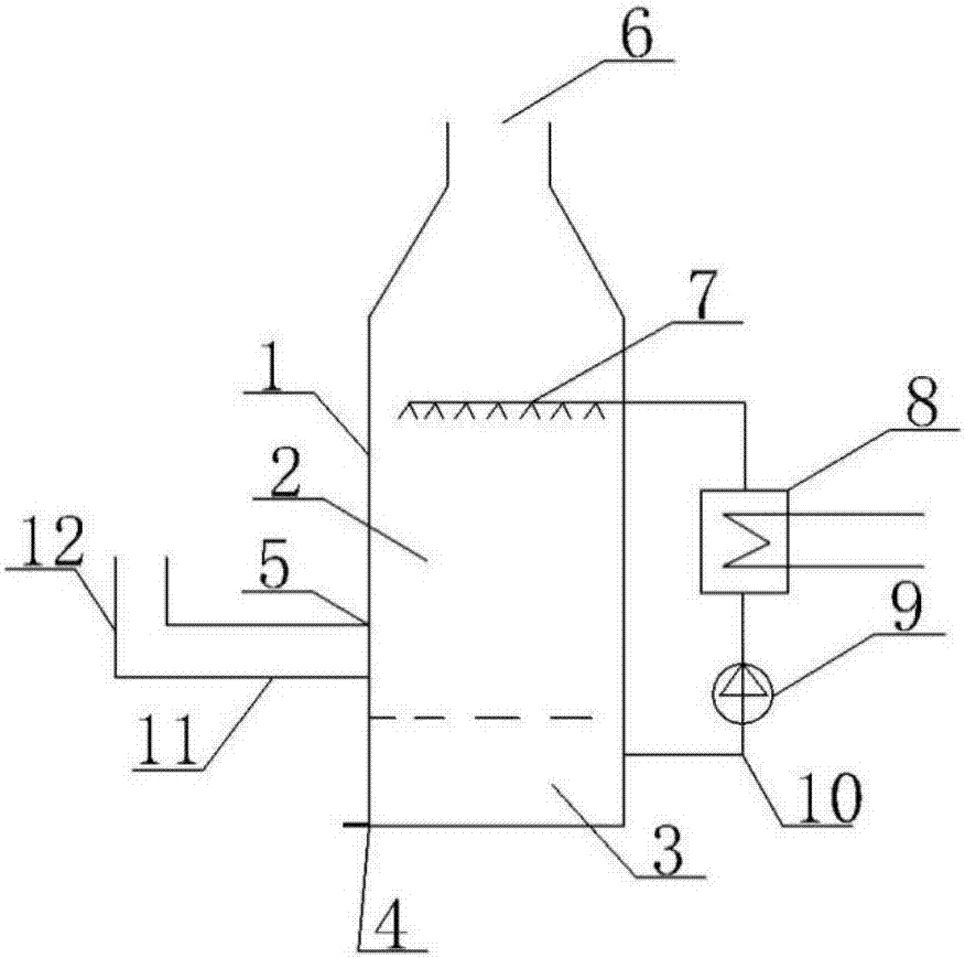
[0024] Such as figure 1 As shown, a wastewater concentrating device includes a tower body; the tower body is provided with an evaporation chamber and a tower pond connected with the evaporation chamber; the evaporation chamber is arranged above the tower pond; the tower pond is provided with a dope outlet The lower part of the evaporation chamber or the upper part of the tower pool is provided with a flue gas inlet, the upper part of the evaporation chamber is provided with a flue gas outlet, and the tower body between the flue gas inlet and the flue gas outlet is provided with a first spray device, so A waste water heater and a circulating pump are connected between the first spraying device and the tower pool through pipelines, and a waste water feed port is provided on the tower body or a channel communicating with the tower body. The waste water heater is heated by flue gas, and the waste water heater is arranged in the flue. When in use, the waste water in the waste water...
Embodiment 2
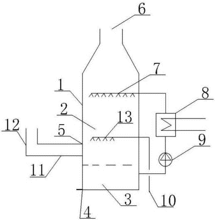
[0032] Such as figure 2 As shown, a wastewater concentrating device includes a tower body; the tower body is provided with an evaporation chamber and a tower pond connected with the evaporation chamber; the evaporation chamber is arranged above the tower pond; the tower pond is provided with a dope Outlet; the lower part of the evaporation chamber or the upper part of the tower pool is provided with a flue gas inlet, the upper part of the evaporation chamber is provided with a flue gas outlet, and the tower body between the flue gas inlet and the flue gas outlet is provided with a first spray device, A waste water heater and a circulating pump are connected between the first spraying device and the tower pool through pipelines, and a waste water feed port is provided on the tower body or a channel communicating with the tower body. A second spraying device is provided between the flue gas inlet and the first spraying device, and the second spraying device communicates with th...
Embodiment 3
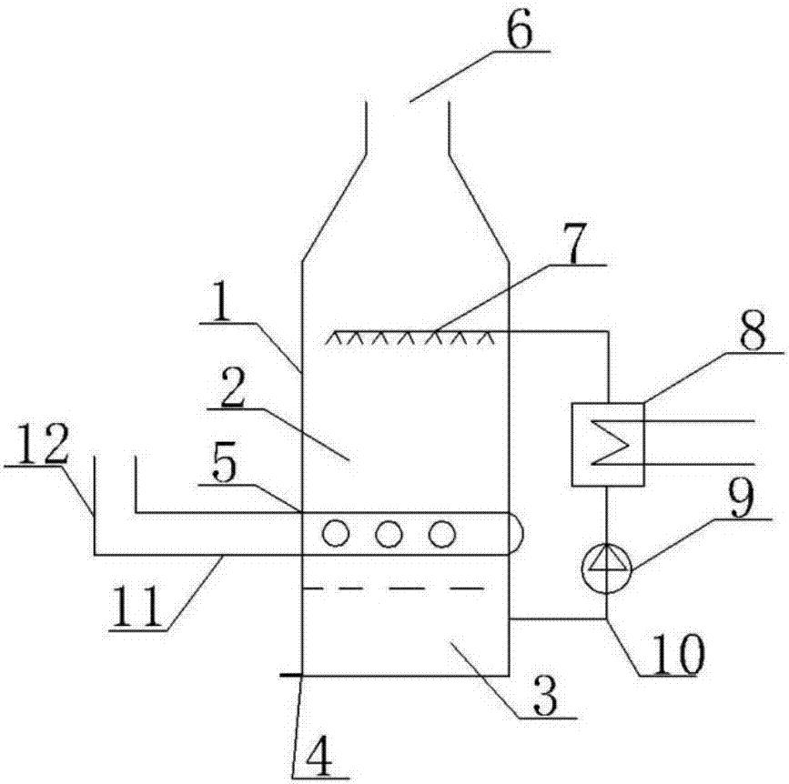
[0037] Such as image 3 As shown, a wastewater concentrating device includes a tower body; the tower body is provided with an evaporation chamber and a tower pond connected with the evaporation chamber; the evaporation chamber is arranged above the tower pond; the tower pond is provided with a dope Outlet; the lower part of the evaporation chamber or the upper part of the tower pool is provided with a flue gas inlet, the upper part of the evaporation chamber is provided with a flue gas outlet, and the tower body between the flue gas inlet and the flue gas outlet is provided with a first spray device, A waste water heater and a circulating pump are connected between the first spraying device and the tower pool through pipelines, and a waste water feed port is provided on the tower body or a channel communicating with the tower body. There are two or more flue gas inlets; all the flue gas inlets are arranged in a balanced manner in the vertical projection direction of the tower ...
PUM
 Abstract
Description
Claims
Application Information
 - R&D
- Intellectual Property
- Life Sciences
- Materials
- Tech Scout
- Unparalleled Data Quality
- Higher Quality Content
- 60% Fewer Hallucinations
Browse by: Latest US Patents, China's latest patents, Technical Efficacy Thesaurus, Application Domain, Technology Topic, Popular Technical Reports.
© 2025 PatSnap. All rights reserved.Legal|Privacy policy|Modern Slavery Act Transparency Statement|Sitemap|About US| Contact US: help@patsnap.com