Breather for transformers

A respirator and transformer technology, applied in the field of transformer equipment, can solve the problems of desiccant oil film adhesion, clogging of drying cylinders, contamination of components, etc., to achieve the effect of prolonging service life, saving maintenance costs, and maintaining smooth airflow

Pending Publication Date: 2017-12-08
HANGZHOU KELIN ELECTRIC POWER EQUIP
View PDF11 Cites 4 Cited by
  • Summary
  • Abstract
  • Description
  • Claims
  • Application Information

AI Technical Summary

Problems solved by technology

Due to the thermal expansion and high pressure of the oil tank, the gas exhaled from the oil tank contains oil, which will contaminate the desiccant in the drying chamber and the components installed in the drying cylinder, affecting the hygroscopic performance of the desiccant, and long-term oil pollution may cause the oil film of the desiccant Adhesion, clogging the drying cylinder, causing poor breathing of the fuel tank

Method used


Image

  • Breather for transformers
  • Breather for transformers
  • Breather for transformers

Examples


Embodiment Construction

[0019] Below, the present invention will be further described in conjunction with the accompanying drawings and specific implementation methods. It should be noted that, under the premise of not conflicting, the various embodiments described below or the technical features can be combined arbitrarily to form new embodiments. .

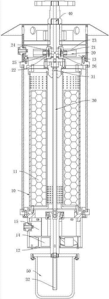
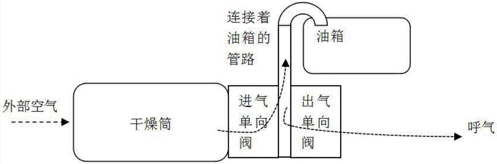
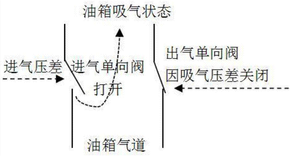
[0020] Such as figure 1 As shown, a transformer respirator includes a drying cylinder 10, and also includes an air inlet passage 20 and an air outlet passage 30. The air inlet passage 20 communicates with the fuel tank air passage 40, and the air inlet passage 20 is provided with a flow direction from the respirator. The outside points to the air intake check valve 21 of the fuel tank air passage 40, and the air intake passage 20 communicates with the drying cylinder 10; the air outlet passage 30 is provided with an air outlet check valve 31 whose flow direction is from the fuel tank air passage 40 to the outside of the respirator, One end of the air ...


PUM


Abstract

The invention discloses a breather for transformers and solves the problem that since exhaust and suction passages of an existing breather for transformers are not separated, oil-bearing gas exhausted by an oil tank of a transformer passes by a drying barrel and contaminate a drying agent. The breather comprises a drying barrel and also comprises an intake passage and an exhaust passage, the suction passage is communicated with a gas passage of an oil tank, the intake passage is provided with an intake one-way valve that has a flow direction from the outside of the breather toward the gas passage of the oil tank, the intake passage is communicated with the drying barrel, the exhaust passage is provided with an exhaust one-way valve that has a flow direction from the gas passage of the oil tank toward the outside of the breather, one end of the exhaust passage is communicated with the gas passage of the oil tank, the other end of the exhaust passage is communicated with the outside of the breather, and the exhaust passage is isolated from the drying agent in the drying barrel. The breather has the advantages that the intake passage and the exhaust passage are separated in order to directly discharge oil-bearing gas exhausted by the oil tank of the transformer out of the breather, the service life of the drying agent is greatly extended, smoothness of a gas flow in the breather is maintained for long time, and maintenance cost is reduced.

Description

technical field [0001] The invention relates to a transformer device, in particular to a transformer respirator. Background technique [0002] At present, for high-voltage electrical equipment filled with insulating oil, such as transformers, reactors, etc., the oil tank will expand and contract due to temperature changes, resulting in changes in the oil level of the oil tank. Respirators are required to balance the air pressure difference inside and outside the tank. At present, in the respirator used in the transformer oil tank, the exhaled gas and the inhaled gas of the oil tank generally pass through the desiccant air chamber, that is, both exhalation and inhalation pass through the same airway. Due to the thermal expansion and high pressure of the oil tank, the gas exhaled from the oil tank contains oil, which will contaminate the desiccant in the drying chamber and the components installed in the drying cylinder, affecting the hygroscopic performance of the desiccant, ...

Claims


Application Information

Patent Timeline
Patent Type & Authority Applications(China)
IPC IPC(8): H01F27/14
CPCH01F27/14
Inventor 郑宏赵健鲍美军陆俊英王根东
Owner HANGZHOU KELIN ELECTRIC POWER EQUIP
Why Eureka
Try Eureka