General galvanometer and visual speed measurement-based flying marking system and control method

A technology of flight marking and control method, which is applied in the field of flight marking system and control, can solve the problems of infeasibility, inability to apply speed, high hardware cost, etc., and achieve the effects of reducing production cost, improving production efficiency and wide versatility

Pending Publication Date: 2017-12-12
GUANGDONG UNIV OF TECH
6 Cites 4 Cited by

AI-Extracted Technical Summary

Problems solved by technology

However, the disadvantage of the above technical solution is that the real-time performance of the system is not high, so the system accuracy is not high, and it cannot be applied to marking occasions with unstable speed
At present, another new type of compensation scheme is to use hardware for compensation. This technical scheme has high precision, but it has high requirements on the at...

Method used

[0055] In addition, the present invention has better versatility based on the flying marking system of the universal vibrating mirror and visual speed measurement. Since most of the laser marking control card 4 and scanning galvanometer 2 interface protocols use the XY2-100 protocol for communication, the technical solution of the present invention uses the general galvanometer protocol to truncate the data of the laser marking control card 4 and recalculate Then it is sent to the scanning galvanometer 2 without any modification to the existing laser marking system. Through plug and play, it can be applied to most of the laser marking systems on the market, so it has wider versatility.
[0056] The present invention is based on a general galvanometer and a visual speed measurement flight marking system with faster speed and higher precision. The technical scheme of the present invention adopts a data reverse compensation method to convert the displacement of the conveyor belt 1 into the movement data of the scanning galvanometer 2, and superimpose it on the X direction for reverse compensation. Since the system of the present invention uses data compensation, the speed of the conveyor belt will only affect the size of the compensation data. Therefore, the technical solution of the present invention breaks throug...

Abstract

The invention discloses a general galvanometer and visual speed measurement-based flying marking system and a control method. The general galvanometer and visual speed measurement-based flying marking system comprises a laser device, a laser marking control card, an upper computer, a data controller and a digital camera and a scanning galvanometer which are arranged on a conveying belt, wherein the data controller is connected with the scanning galvanometer, the laser marking control card and the digital camera; the laser marking control card is also connected with the upper computer; the data controller blocks data between the laser marking control card and the scanning galvanometer; a to-be-marked workpiece picture shot by the digital camera is processed to obtain affine transformation parameters; and the data controller corrects blocked machining data and converts the data into a digital square wave signal which is sent to the scanning galvanometer to adjust the laser device for marking. Compared with the prior art, the general galvanometer and visual speed measurement-based flying marking system has the advantages of higher generality, higher speed, higher precision and capability of reducing the production cost and improving the production efficiency; and furthermore, the production cost can be reduced, the production efficiency can be improved, and the working intensity of a worker is reduced.

Application Domain

Technology Topic

Image

  • General galvanometer and visual speed measurement-based flying marking system and control method
  • General galvanometer and visual speed measurement-based flying marking system and control method

Examples

  • Experimental program(1)

Example Embodiment

[0031] The technical solutions in the embodiments of the present invention will be clearly and completely described below with reference to the accompanying drawings in the embodiments of the present invention. Obviously, the described embodiments are only a part of the embodiments of the present invention, not all of the embodiments. Based on the embodiments of the present invention, all other embodiments obtained by those of ordinary skill in the art without creative efforts shall fall within the protection scope of the present invention.
[0032] It should be noted that if there are directional indications (such as up, down, left, right, front, back, etc.) involved in the embodiments of the present invention, the directional indications are only used to explain a certain posture (as shown in the accompanying drawings). If the specific posture changes, the directional indication also changes accordingly.
[0033] In addition, if there are descriptions involving "first", "second", etc. in the embodiments of the present invention, the descriptions of "first", "second", etc. are only used for the purpose of description, and should not be construed as indicating or implying Its relative importance or implicitly indicates the number of technical features indicated. Thus, a feature delimited with "first", "second" may expressly or implicitly include at least one of that feature. In addition, the technical solutions between the various embodiments can be combined with each other, but must be based on the realization by those of ordinary skill in the art. When the combination of technical solutions is contradictory or cannot be realized, it should be considered that the combination of such technical solutions does not exist. , is not within the scope of protection required by the present invention.
[0034] The invention proposes a flying marking system based on a universal galvanometer and visual speed measurement.
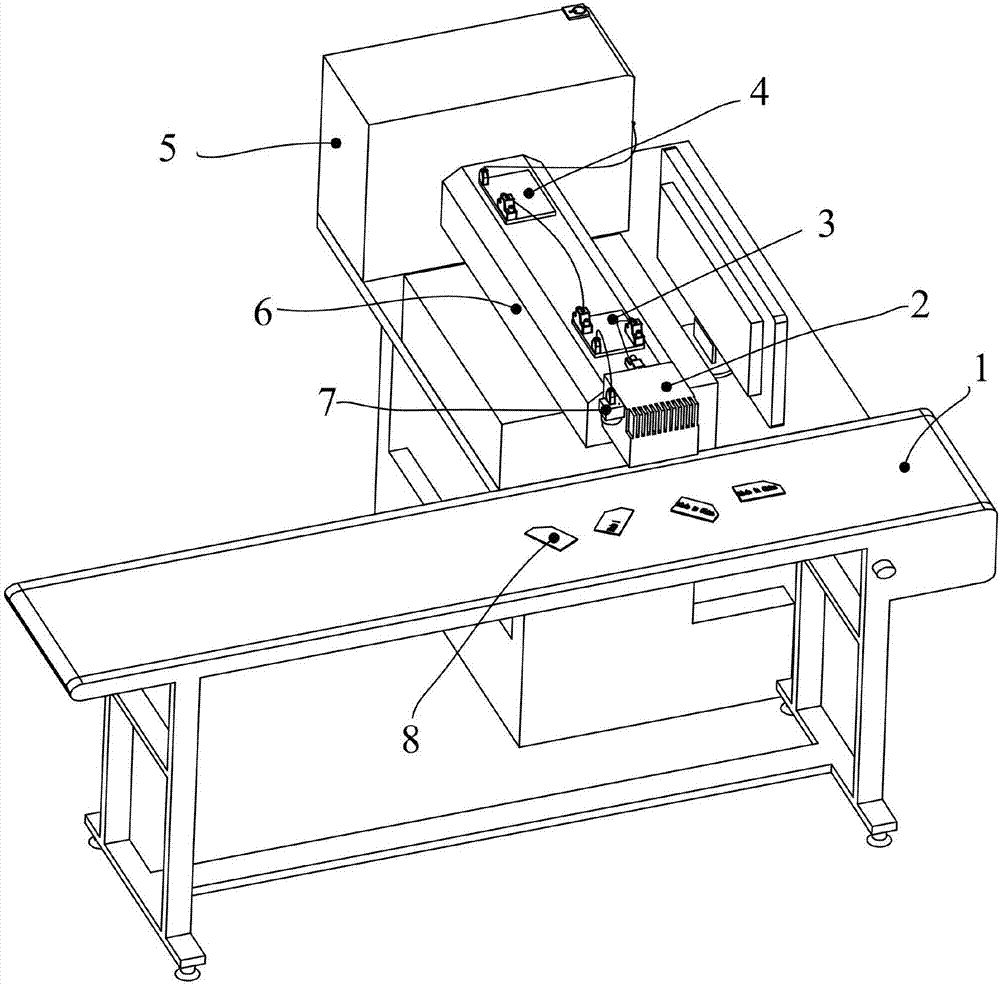
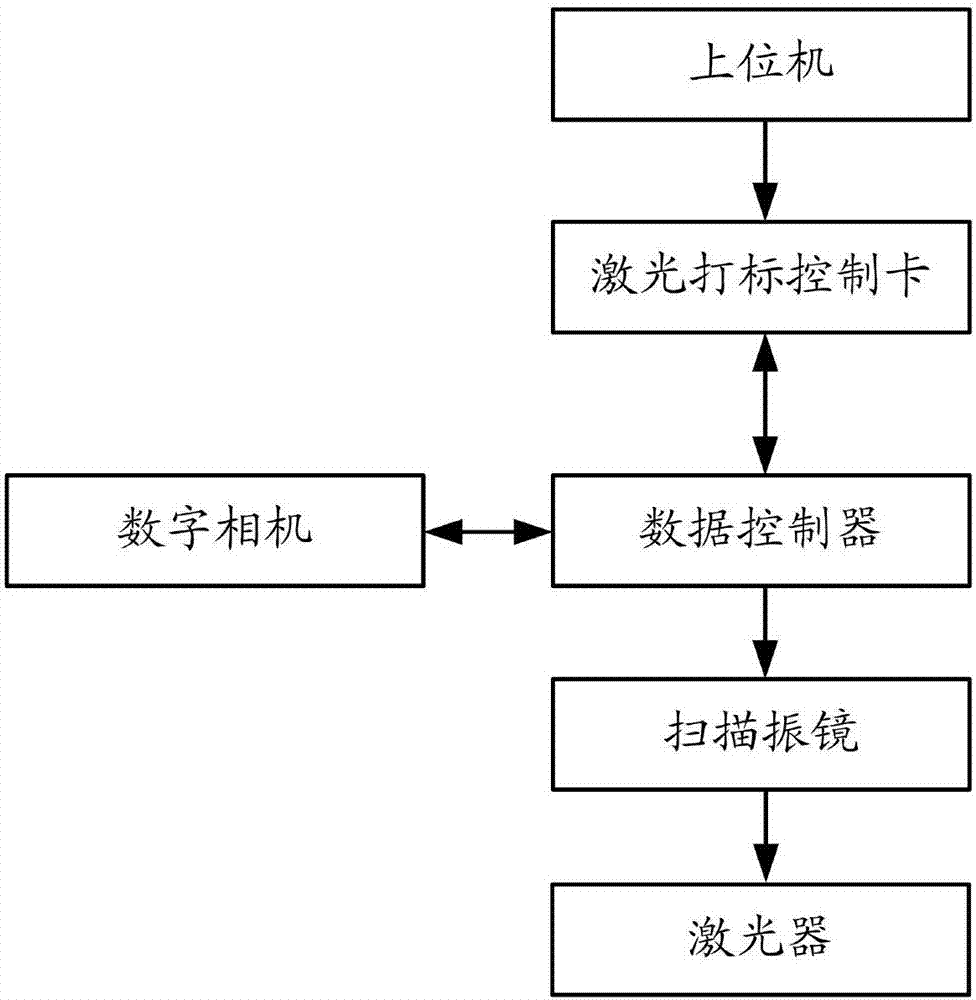
[0035] See figure 1 and figure 2 , the flying marking system based on the general galvanometer and visual speed measurement according to the embodiment of the present invention includes a laser 6, a laser marking control card 4, a host computer 5, a data controller 3 and a digital camera 7 arranged above the conveyor belt 1 and a scanning The galvanometer 2; the data controller 3 is respectively connected with the scanning galvanometer 2, the laser marking control card 4 and the digital camera 7, and the laser marking control card 4 is also connected with the host computer 5; the data controller 3 connects the laser marking control card Data interception between 4 and the scanning galvanometer 2, after processing the picture of the workpiece to be marked 8 captured by the digital camera 7 to obtain the affine transformation parameters, the data controller 3 corrects the intercepted processing data and converts it into a digital square. The wave signal is sent to the scanning galvanometer 2 to adjust the laser 6 for marking.
[0036]Preferably, the laser marking control card 4 in the embodiment of the present invention communicates with the host computer 5 through a USB port, and the laser marking control card 4 and the scanning galvanometer 2 and the data controller 3 are connected through the DB25 interface and through the XY2 interface. -100 protocol communication.
[0037] Preferably, the affine transformation parameters in the embodiment of the present invention include position parameters ΔX, ΔY and rotation parameters θ of the workpiece 8 to be marked relative to the standard template position, and the conveying speed v of the conveyor belt.
[0038] Preferably, the conveying speed v of the conveyor belt in the embodiment of the present invention is the ratio between the distance L1 between the digital camera 7 continuously taking two pictures of the moving workpiece 8 to be marked and the time interval t1 when the digital camera 7 takes two pictures.
[0039] The present invention also proposes a control method using a flying marking system based on a universal galvanometer and visual speed measurement, the steps of which include: intercepting the processing data, using the universal galvanometer protocol to obtain original data, and then using a data compensation method to The displacement is converted into the movement data of the scanning galvanometer 2 and superimposed on the X direction for reverse compensation, the position information is collected and the affine transformation parameters are obtained and converted into new data synchronously, and sent to the scanning galvanometer 2 through the general protocol to adjust the laser 6. mark.
[0040] Specifically, the control method of the embodiment of the present invention includes the following steps:
[0041] S1 data acquisition: collect laser marking control card 4 data and obtain X/Y processing data, affine transformation parameters, conveyor belt transmission speed v;
[0042] S2 Calculate new data: Calculate the X/Y data using the affine transformation formula and the data inverse compensation algorithm. The affine transformation parameters include θ, ΔX, and ΔY, and the compensation equivalent includes the compensation value ΔN, which is converted to the actual value through the conveying speed v of the conveyor belt. The movement equivalent of the scanning galvanometer 2 and the new coordinate data X'Y', where X' and Y' are respectively:
[0043] X′=X·cosθ+Y·sinθ+ΔX+ΔN
[0044] Y′=Y·cosθ-X·sinθ+ΔY
[0045] S3 sends new coordinate data: The data controller 3 simulates the XY2-100 protocol, and sends new data to the scanning galvanometer 2 to adjust the laser 6 for marking.
[0046] The affine transformation parameters θ, ΔX, and ΔY in the embodiment of the present invention are determined by the current posture of the workpiece 8 to be marked and the position coordinates of the standard template. Preferably, the position coordinates are coordinates in an image coordinate system, and the origin of the position coordinates is the image origin.
[0047] The compensation value ΔN in the embodiment of the present invention is calculated by the laser switching control time Δt, the scaling factor s between the actual physical length and the data span of the scanning galvanometer 2, and the conveying speed v of the conveyor belt. The calculation formula is: ΔN=v·Δt/s.
[0048] The working principle of the flying marking system based on the general galvanometer and visual speed measurement in the embodiment of the present invention is:
[0049] First start the marking system, set the marking pattern in the software of the host computer 5 and adjust the size of the pattern, place the standard workpiece on the upper surface of the conveyor belt 1 accurately, and the conveyor belt 1 is in a static state at this time, and then manually move the conveyor belt 1 Move the object under the scanning galvanometer 2 for stationary marking. Then continuously adjust the size and position of the pattern in the host computer 5, and then manually mark until the marked pattern is satisfactory, and save the pattern in the software, and the laser marking control card 4 at this time already includes the pattern. processing data. After manually moving the workpiece into the shooting range of the digital camera 7, and aligning the geometric center of the standard workpiece with the shooting center of the digital camera 7 as much as possible, a template image is shot.
[0050] Then the conveyor belt 1 is turned on and the workpiece 8 to be marked is placed on the upper surface of the conveyor belt 1 at random. When the workpiece enters the shooting range of the digital camera 7, the digital camera 7 will take several pictures of the workpiece 8 to be marked at the forefront, and The picture is analyzed and processed to calculate the rotation parameters ΔX, ΔY and θ of the workpiece 8 to be marked, and the conveying speed v of the conveyor belt 1 is calculated according to the shooting interval time of the digital camera 7, and sent to the data controller 3. At the same time, when the picture meets certain conditions, the marking switch is triggered. When the data controller 3 obtains the rotation parameters ΔX, ΔY, θ and the conveying speed v of the conveyor belt and starts timing, the digital camera 7 enters the trigger wait until the next workpiece to be marked arrives again.
[0051] When the data controller 3 finishes timing, the workpiece 8 to be marked enters the line of sight of the scanning galvanometer 2, and at the same time the laser marking control card 4 sends the marking data, and the data controller 3 sends the marking data to the laser marking control card through the XY2-100 protocol. 4. Carry out data collection to obtain real-time processing data. Then, the real-time affine transformation calculation is performed on the processing data, and the compensated flight data is added to the X-axis direction to obtain the calculated new processing data.
[0052] Finally, use the XY2-100 protocol to simulate the new data, and use the DB25 interface to send it to the scanning galvanometer 2. At this time, the laser 6 of the laser marking machine marks the ideal image in real time without distortion.
[0053] The flying marking system based on the general galvanometer and visual speed measurement of the technical solution of the present invention uses the digital camera 7 to detect the moving workpiece 8 to be marked, and performs soft triggering on it, instead of the photoelectric triggering system, at this time, the laser marking will be triggered. Then the laser marking control card 4 sends the X/Y axis processing data of the scanning galvanometer 2 to be truncated, and the data is collected according to the general galvanometer protocol, and the obtained processing data is sent to the data Controller 3. The visual speed measurement is used to replace the coded speed measurement, and more accurate forward speed and position information of the object can be obtained, and the position information and speed are sent to the data controller 3 . The data controller 3 performs data calculation on the position information through affine transformation to obtain new data. Then carry out the flight calculation for the X direction in the new data, and obtain the new processing data in the X direction when flying marking. The final processing data is re-sent to the scanning galvanometer 2 to adjust the laser 6 for processing according to the general galvanometer protocol.
[0054] Therefore, compared with the flying marking system in the prior art, the system of the embodiment of the present invention removes the photoelectric trigger system and the encoder for the speed measurement system, and uses the digital camera 7 to trigger and measure the speed to obtain the position information relative to the template. At the same time, a data controller 3 is also added for data collection, calculation and transmission. The data acquisition and transmission adopts the general galvanometer protocol XY2-100. The data calculation follows the affine transformation principle and the flight data inverse compensation principle. The data inverse compensation principle is based on the speed of the conveyor belt and the corresponding scanning galvanometer in single-point marking. time is jointly determined.
[0055] In addition, the flight marking system based on the universal galvanometer and visual speed measurement of the present invention has better versatility. Since most of the interface protocols of the laser marking control card 4 and the scanning galvanometer 2 use the XY2-100 protocol for communication, the technical solution of the present invention truncates the data of the laser marking control card 4 through the general galvanometer protocol, and recalculates the data. It is then sent to the scanning galvanometer 2 without any modification to the existing laser marking system. Through plug and play, it can be applied to most laser marking systems on the market, so it has wider versatility.
[0056] The flying marking system based on the universal galvanometer and the visual speed measurement of the present invention has faster speed and higher precision. The technical scheme of the present invention adopts a data inverse compensation method to convert the displacement of the conveyor belt 1 into the data of the movement of the scanning galvanometer 2, and superimpose it in the X direction for reverse compensation. Since the system of the present invention adopts data compensation, the speed of the conveyor belt will only affect the size of the compensation data. Therefore, the technical solution of the present invention breaks through the bottleneck of the speed of the conveyor belt 1. In theory, as long as the moving speed of the scanning galvanometer 2 is large enough, the marking will be completed. At any speed, the workpiece 8 can be marked with a pattern that is consistent with the static marking, so it has a faster speed and higher precision than the prior art.
[0057] The flying marking system based on the universal galvanometer and the visual speed measurement of the present invention can improve the production efficiency. In the traditional flying marking system, a fixture mold for stabilizing and regulating the workpiece 8 to be marked is generally arranged in front of the conveyor belt 1 , and the fixture mold is generally a precision mold, so the price is relatively expensive. The technical scheme of the present invention uses a digital camera 7 to replace the traditional photoelectric trigger system and coded speed measurement system, which can not only trigger and measure the speed, but also obtain the position information of the object. Both can mark the ideal pattern, so the traditional fixture module is not needed to correct the position of the workpiece, which can reduce the production cost, improve the production efficiency and reduce the labor intensity of workers.
[0058] The above descriptions are only preferred embodiments of the present invention, and are not intended to limit the scope of the present invention. Under the conception of the present invention, the equivalent structural transformations made by the contents of the description and accompanying drawings of the present invention, or directly/indirectly applied in Other related technical fields are included within the scope of patent protection of the present invention.

PUM

no PUM

Description & Claims & Application Information

We can also present the details of the Description, Claims and Application information to help users get a comprehensive understanding of the technical details of the patent, such as background art, summary of invention, brief description of drawings, description of embodiments, and other original content. On the other hand, users can also determine the specific scope of protection of the technology through the list of claims; as well as understand the changes in the life cycle of the technology with the presentation of the patent timeline. Login to view more.

Similar technology patents

A Coherent Target Decomposition Method Based on Scattering Matrix

ActiveCN102262223AGood versatilityImprove accuracyRadio wave reradiation/reflectionScatter matrixPolarimetric sar
Owner:CENT FOR EARTH OBSERVATION & DIGITAL EARTH CHINESE ACADEMY OF SCI

Classification and recommendation of technical efficacy words

  • Wide versatility
  • Good versatility

Device and method for detecting water flow of gas tubine cooling blade

InactiveCN1858560ASimple device structureWide versatilityVolume/mass flow by electromagnetic flowmetersElectricityGas turbines
Owner:SHENYANG LIMING AERO-ENGINE GROUP CORPORATION

Image recognition method and system

Owner:新方正控股发展有限责任公司 +1
Why Eureka
Try Eureka