Microwave thermoacoustic detecting and monitoring system and method

A monitoring system and acoustic detection technology, which is applied in the fields of structural health monitoring, non-destructive testing and fault diagnosis, can solve the problems that the overall evaluation effect cannot be fully utilized, the acoustic emission signal cannot be enhanced, and the acoustic emission signal cannot be reproduced. Improve rapid defect imaging and quantitative capabilities, high monitoring efficiency, and achieve enhanced and reproducible effects

Active Publication Date: 2017-12-12
CHANGSHA UNIVERSITY
View PDF14 Cites 7 Cited by
  • Summary
  • Abstract
  • Description
  • Claims
  • Application Information

AI Technical Summary

Problems solved by technology

[0008] Acoustic emission has some disadvantages, such as the signal is very weak, susceptible to noise interference, and it is difficult to quantify defects
The existing acoustic emission technology mainly uses amplifier circuits to amplify the acoustic emission signal, which cannot enhance the acoustic emission signal at the source, let alone reproduce the acoustic emission signal of static defects
Therefore, only dynamic defects can be monitored, and active detection cannot be realized
The detection data obtained by using other detection methods is decoupled from the acoustic emission monitoring data, lacks an organic combination, and the overall evaluation effect cannot be fully utilized

Method used


Image

  • Microwave thermoacoustic detecting and monitoring system and method
  • Microwave thermoacoustic detecting and monitoring system and method
  • Microwave thermoacoustic detecting and monitoring system and method

Examples


Embodiment Construction

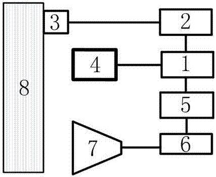
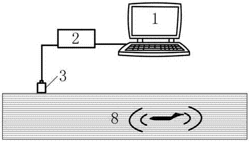
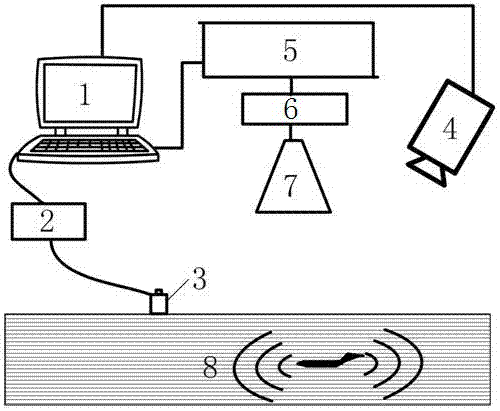
[0041] Such as Figure 1 to Figure 3 As shown, the microwave thermoacoustic detection and monitoring system includes a control system 1, an acoustic emission detector 2, an acoustic emission sensor array 3, a thermal imager 4, a microwave signal generator 5, a microwave signal amplifier 6 and a microwave antenna 7. The acoustic emission The sensor array 3 is arranged on the object 8 to be inspected, the field of view of the thermal imager 4 covers the area to be inspected of the object 8 to be inspected, the microwave antenna 7 is aimed at the area to be inspected of the object 8 to be inspected, and the acoustic emission sensor array 3. The acoustic emission detector 2 is electrically connected to the control system 1. The control system 1 is electrically connected to the microwave antenna 7 through the microwave signal generator 5 and the microwave signal amplifier 6. The control system 1 is electrically connected to the thermal imager 4.

[0042] The acoustic sensors in the...


PUM


Abstract

The invention discloses a microwave thermoacoustic detecting and monitoring system and method. The microwave thermoacoustic detecting and monitoring system comprises an acoustic emission sensor array, an acoustic emission detector, a control system, a thermal imager, a microwave signal generator, a microwave signal amplifier and a microwave antenna, wherein the acoustic emission sensor array is arranged on a detected object; the field of view of the thermal imager covers a to-be-detected area of the detected object; the microwave antenna is aligned with the to-be-detected area of the detected object; the acoustic emission sensor array is electrically connected with the control system through the acoustic emission detector; and the control system is electrically connected with the microwave antenna through the microwave signal generator and the microwave signal amplifier in sequence and also electrically connected with the thermal imager. The microwave thermoacoustic detecting and monitoring system can realize not only on-line real-time monitoring but also recurrence and quantification of defect locations, and is wide in monitoring range, high in detection sensitivity and reliable in detection result.

Description

technical field [0001] The invention belongs to the fields of structural health monitoring, non-destructive testing and fault diagnosis, and particularly relates to a microwave thermoacoustic testing and monitoring system and method. Background technique [0002] With the development of modern science and industrial technology, non-destructive testing and health monitoring technology has become a necessary means to ensure product quality and operational safety. The detection and quality control of large structural components and equipment is becoming a difficult point in the field of non-destructive testing and structural health monitoring. In order to ensure the reliability of the detection and monitoring results, it is generally required that the monitoring system can run continuously, and the detection system has visualization and high accuracy. features. [0003] Non-destructive testing and health monitoring technologies for metal materials, concrete materials and compo...

Claims


Application Information

Patent Timeline
Patent Type & Authority Applications(China)
IPC IPC(8): G01N25/72G01N29/14
CPCG01N25/72G01N29/14
Inventor 杨瑞珍何赟泽
Owner CHANGSHA UNIVERSITY
Why Eureka
Try Eureka