
Radial ultrasonic vibration auxiliary cutting device

A cutting device and ultrasonic vibration technology, which is applied to the details of milling machine equipment, metal processing equipment, milling machine equipment, etc., can solve the problems of complex structure, high cost, inconvenient disassembly and assembly of the device, and achieve the expansion of processing range, simple structure, and convenient installation Effect

Inactive Publication Date: 2017-12-15
NORTHEASTERN UNIV LIAONING
View PDF7 Cites 7 Cited by
  • Summary
  • Abstract
  • Description
  • Claims
  • Application Information

AI Technical Summary

Problems solved by technology

However, in the research of ultrasonic vibration cutting in the axial and torsional directions, in order to avoid the winding phenomenon of the ultrasonic vibration device during rotation, a collector ring or carbon brush is required to power the transducer, and a large modification of the drilling machine is required , so the structure is complex, resulting in inconvenient disassembly and assembly of the device and high cost

Method used


Image

  • Radial ultrasonic vibration auxiliary cutting device
  • Radial ultrasonic vibration auxiliary cutting device
  • Radial ultrasonic vibration auxiliary cutting device

Examples


Embodiment

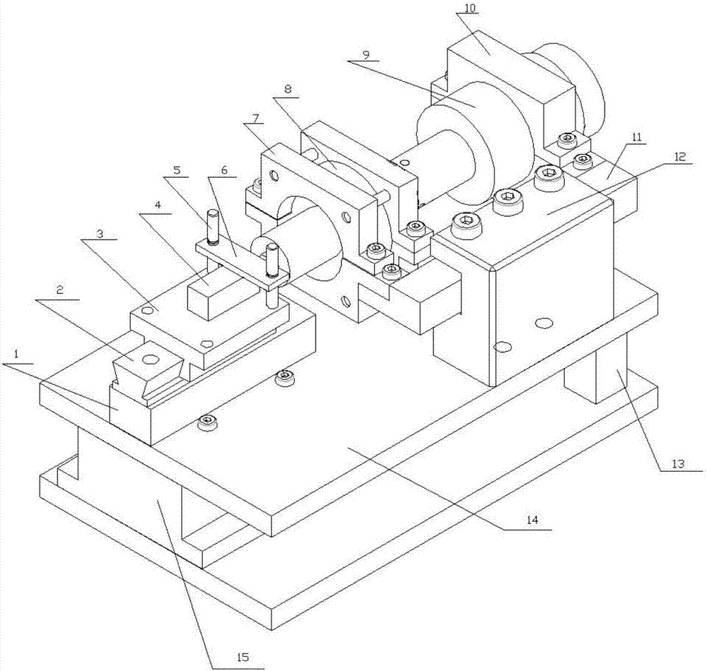
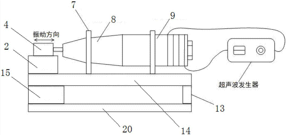
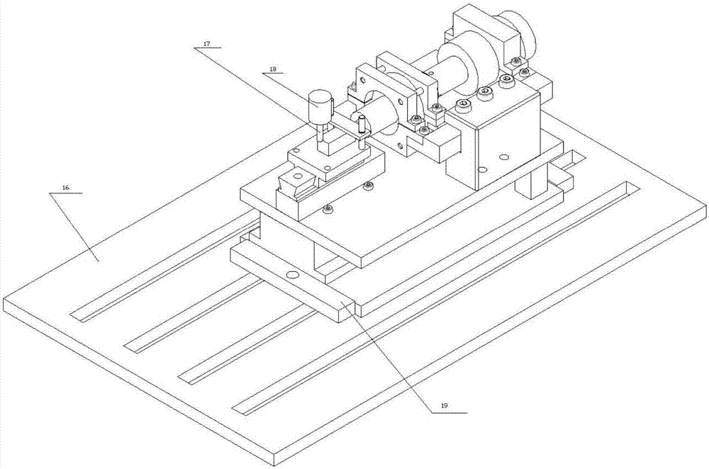
[0035] Use process: In this experiment, the ZJK7532A drilling and milling machine produced by Wuhan No. 4 Machine Tool Factory was used for radial ultrasonic vibration-assisted cutting. The experiment used a high-speed steel straight shank end mill with a diameter of 8mm to process No. 45 steel material, and the workpiece size was 30mm*30mm *60mm. First, the transducer of the present invention is connected to the generator through a wire, and the ultrasonic vibration device is fixed on the fixed block through a cantilever beam device, and the radial ultrasonic vibration is realized by adding an ultrasonic vibration and a rotary motion of the tool in the feed direction Vibration cutting process.

[0036] After starting the ultrasonic generator, the ultrasonic generator transmits the 20kHz ultrasonic excitation signal to the horn 8 through the transducer, and the horn 8 transmits the ultrasonic excitation signal to the workpiece 4, so that the workpiece 4 generates 20kHz in the ...


PUM


Abstract

The invention discloses a radial ultrasonic vibration auxiliary cutting device. The radial ultrasonic vibration auxiliary cutting device comprises a first base plate and a second base plate. The first base plate is fixedly connected with the second base plate through a front support block and a rear support block. A cushion block is fixedly connected to the first base plate through bolts. A fixing block is further fixedly connected to the first base plate through bolts. A cross beam is arranged in a groove of the fixing block through fastening bolts. The cross beam and the cushion block are arranged on a central line in a corresponding manner. The cushion block is provided with a guide rail, and a slide block is in sliding fit with the guide rail. A cover plate is fixedly connected to the end of the slide block through double-end studs. A workpiece is put on the slide block and located through the cover plate. A front support is fixedly connected to the cross beam through bolts. A pore channel is formed by the front support and the cross beam, wherein the pore channel allows an amplitude-change pole to pass through. A rear support is fixedly connected to the cross beam through bolts. A transducer is fixed to the cross beam through the rear support and connected with the amplitude-change pole. The workpiece is fixedly connected to the end of the amplitude-change pole. By means of the radial ultrasonic vibration auxiliary cutting device, radial ultrasonic vibration auxiliary cutting and measurement of cutting force applied in the machining process are achieved; and the radial ultrasonic vibration auxiliary cutting device is convenient to design, easy to machine and easy and convenient to mount and demount.

Description

technical field [0001] The invention belongs to the technical field of ultrasonic vibration processing, in particular to a radial ultrasonic vibration assisted cutting device. Background technique [0002] With the development of aerospace, national defense, modern medicine and bioengineering technology, there are more and more demands for miniaturization, miniaturization equipment and micro-sized parts, and the requirements for shape accuracy, dimensional accuracy and surface quality are extremely high. Manufacturing technology has brought severe challenges. The research and development of precision machining, ultra-precision micro-machining and nano-machining technology has become an important development direction of modern manufacturing technology. Japanese scholar Junichiro Kumabe was the first to expound the mechanism and application direction of ultrasonic vibration cutting, which laid a theoretical foundation for the research of vibration cutting. Since then, intern...

Claims


Application Information

Patent Timeline
Patent Type & Authority Applications(China)
IPC IPC(8): B23C9/00
CPCB23C9/00
Inventor 邹平任利东何宇赵海东康迪周忠明毛亮
Owner NORTHEASTERN UNIV LIAONING
Learn More