
Vacuumizing structure of compression molding die

A compression molding and vacuuming technology, used in the field of compression molding molds, can solve problems such as poor exhaust, achieve uniform internal quality, good compactness, and improve the qualification rate and quality requirements.

Pending Publication Date: 2017-12-15
WUXI XINHONGTAI ELECTRIC TECH CO LTD
View PDF8 Cites 3 Cited by
  • Summary
  • Abstract
  • Description
  • Claims
  • Application Information

AI Technical Summary

Problems solved by technology

[0004] The purpose of the present invention is to provide a vacuum-pumping structure for a compression molding mold, which can quickly extract the gas generated in the mold cavity during the product molding process, so as to solve the problem caused by the poor exhaust of the compression molding mold in the prior art. gas problem

Method used


Image

  • Vacuumizing structure of compression molding die
  • Vacuumizing structure of compression molding die
  • Vacuumizing structure of compression molding die

Examples


Embodiment Construction

[0017] The technical solutions of the present invention will be further described below in conjunction with the accompanying drawings and through specific implementation methods.

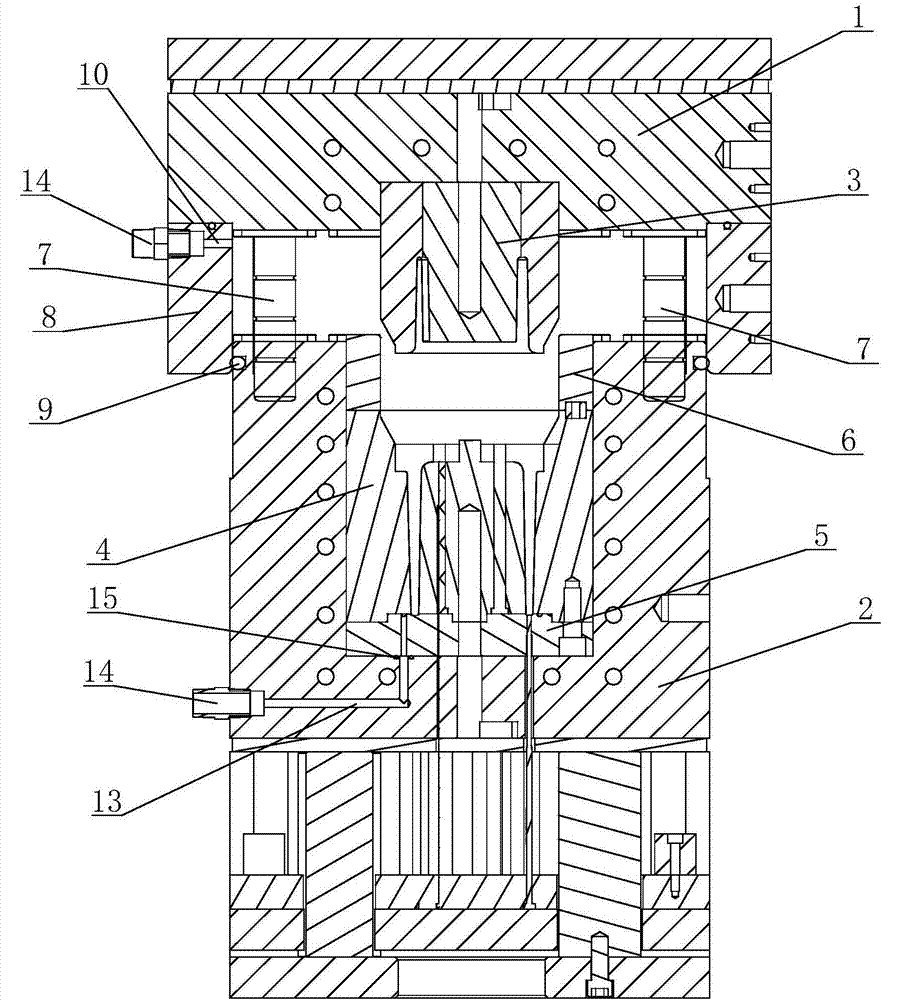
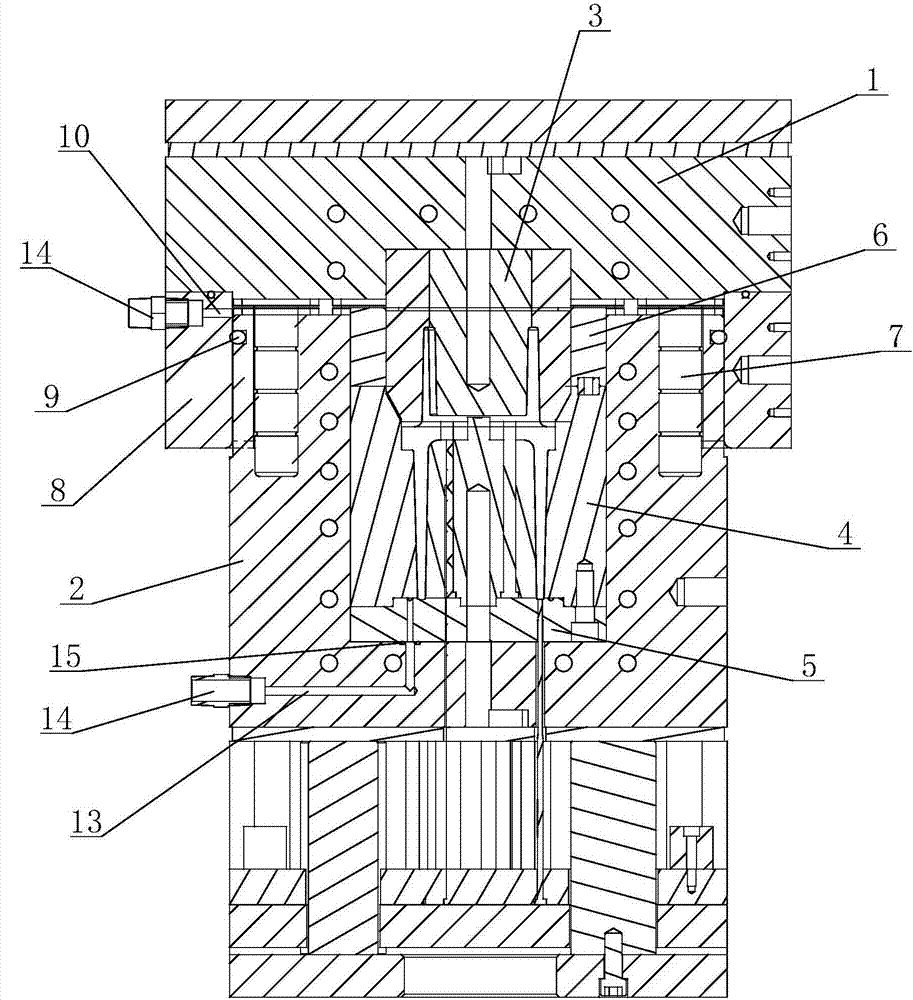
[0018] see Figure 2 to Figure 4 As shown, in this embodiment, a vacuum pumping structure of a compression molding mold includes an upper mold 1 and a lower mold 2 arranged in cooperation, and an upper mold core 3 is arranged at the center of the upper mold 1, corresponding to the upper mold core 3. A mold cavity 4 is provided on the lower mold 2, a lower mold core 5 is provided at the bottom of the mold cavity 4, and the top of the mold cavity 4 is a feeding chamber 6, and the upper mold 1 and the lower mold 2 Several guide posts 7 are arranged between them.

[0019] The bottom of the upper mold 1 is provided with a sealing sleeve 8, the inner diameter of the sealing sleeve 8 is set in accordance with the outer diameter of the lower mold 2, and the top of the lower mold 2 is equipped with a first ...


PUM


Abstract

The invention discloses a vacuumizing structure of a compression molding die. The vacuumizing structure comprises an upper die and a lower die, wherein an upper die core is arranged in the central part of the upper die, and a die cavity is arranged on the lower die; the bottom of the die cavity is provided with a lower die core; and the bottom of the upper die is provided with a sealing sleeve, and a high-temperature-resistant sealing component is arranged between the lower die and the sealing sleeve. When the upper die is closed, the cavity between the upper die and the lower die is sealed through the sealing sleeve. A first vacuumizing channel is formed in the top of the sealing sleeve, and the first vacuumizing channel is connected with a first vacuumizing device through a connector. A second vacuumizing channel communicating with the bottom of the die cavity is formed in the bottom of the lower die, and the second vacuumizing channel is connected with a second vacuumizing device through a connector. The vacuumizing structure of the compression molding die not only is reasonable in structure and simple in processing technology, but also increases the qualified rate and the quality demand of products.

Description

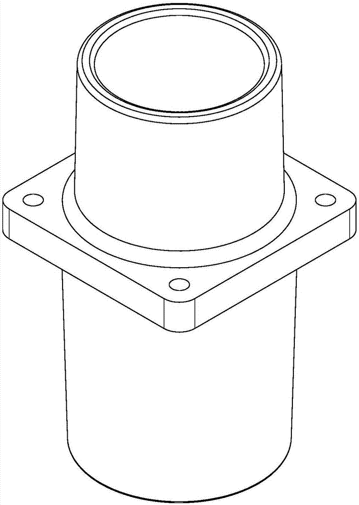
technical field [0001] The invention relates to a compression molding mold, in particular to a vacuum pumping structure of the compression molding mold. Background technique [0002] see figure 1 as shown, figure 1 It is a structural schematic diagram of an existing insulating sleeve. The product is pressed and formed by unsaturated polyester glass reinforced molding compound (collectively referred to as BMC). The product has high requirements in terms of insulation performance and mechanical performance, and the use conditions are relatively complicated; the requirements High dimensional accuracy and high requirements for appearance and surface quality; the appearance of the product is flat, smooth, and free of bubbles, and there must be no white spots, exposed glass fibers, etc.; the upper and lower ports of the product cylinder must not have material shortage or burnt phenomenon; the color of the product meets the requirements ;The interior of the product requires good ...

Claims


Application Information

Patent Timeline
Patent Type & Authority Applications(China)
IPC IPC(8): B29C43/36B29C43/56B29K67/00
CPCB29C43/36B29C43/56B29C2043/563B29K2067/06
Inventor 胡志坚赵敏海王永康
Owner WUXI XINHONGTAI ELECTRIC TECH CO LTD
Learn More