Laser peening composite rolling strengthening surface modification method and device

A laser shot peening and surface modification technology, applied in the field of surface deformation strengthening, can solve problems such as poor surface quality and uneven stress distribution, and achieve the effect of large residual compressive stress

Active Publication Date: 2017-12-15
JIANGSU UNIV
View PDF2 Cites 21 Cited by
  • Summary
  • Abstract
  • Description
  • Claims
  • Application Information

AI Technical Summary

Problems solved by technology

[0005] The purpose of the present invention is to invent a method for surface modification of laser shot peening composite rolling strengthening for the problems of uneven distribution of surface residual stress and poor surface quality induced by the existing laser shot peening process, and at the same time provide a method for Apparatus used for this method

Method used


Image

  • Laser peening composite rolling strengthening surface modification method and device
  • Laser peening composite rolling strengthening surface modification method and device
  • Laser peening composite rolling strengthening surface modification method and device

Examples


Embodiment 1

[0035] like Figure 1-4 shown.

[0036] A method for laser shot peening composite rolling strengthening surface modification, the specific steps are as follows:

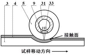
[0037] 1) Grinding and polishing the surface of the workpiece 3 to be strengthened for pretreatment, and then closely attaching 50-200 μm aluminum foil 4 on the surface for later use; Figure 1-2 ;

[0038] 2) Turn on the computer 7, set the laser peening parameters, compile the program to control the X, Y mobile platforms 1, 2, and the hydraulic cylinders 14, 26 and the laser 32 work together;

[0039] 3) By controlling the hydraulic cylinders 14 and 26, the transparent rolling wheel 5 acts on the workpiece 3 positioned on the Y-axis moving platform 2 with a preset load of 200-300 MPa, the surface of the workpiece 3 undergoes initial deformation, and the rolling wheel 5 Contact with the surface of the workpiece 3 with an arc surface, such as image 3 ;

[0040] 4) The laser 32 emits light, and performs laser sh...

Embodiment 2

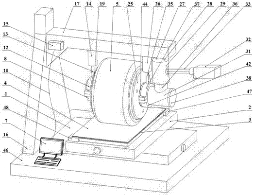
[0046] like Figure 1-2 shown.

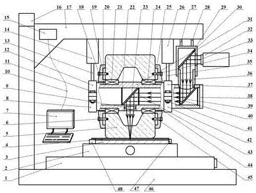
[0047] A device for laser shot peening composite rolling strengthening surface modification, including a control system and a mobile platform controlled by the control system, a hydraulic system, a rolling system, a laser 32 and an optical path system, and the rolling system is under the action of the hydraulic system Compressing produces a preset load on the surface of the workpiece and causes plastic deformation on the surface of the workpiece. The moving platform drives the workpiece to move in the X and Y directions to achieve laser shot peening and rolling strengthening in the entire strengthening area. The laser 32 generates laser light passing through The optical path system is introduced into the main shaft of the rolling system and passes through the transparent rolling wheel through the condenser lens 9 fixed on the main shaft to irradiate the surface of the workpiece to perform laser shot peening on the workpiece. like figure 1 , ...


PUM

PropertyMeasurementUnit
thicknessaaaaaaaaaa
laser intensityaaaaaaaaaa
diameteraaaaaaaaaa

Abstract

The invention discloses a laser peening composite rolling strengthening surface modification method and device. The device comprises a control system, a movable platform, a hydraulic system, a rolling system, a laser and a light path system. According to the device and the method, the hydraulic system is controlled through a computer so as to enable a transparent rolling wheel to roll the surface of a workpiece with a preset load so that the surface of the workpiece can get initial deformation, meanwhile, a light path adjusting system controls the light emitting direction of a short pulse laser beam with the high-peak power density so as to enable the laser beam to vertically irradiate the surface of the workpiece pasted with an aluminum foil through the transparent rolling wheel, an instantaneous plasma shock wave is induced to act on a surface material so as to generate plastic deformation with ultrahigh strain rate, and therefore laser peening and rolling composite strengthening of the workpiece can be achieved. The device and the method have the advantages that the gain effects of laser peening and rolling strengthening can be seamlessly combined, and meanwhile, good surface quality and uniform residual stress distribution can be ensured.

Description

technical field [0001] The invention belongs to the technical field of surface deformation strengthening, and relates to laser shot peening strengthening technology and rolling technology, in particular to a method and device for surface modification of laser shot peening composite rolling strengthening. Background technique [0002] With the development of high-end equipment in the fields of aviation, aerospace, weapons, energy, and transportation, the industry has increasingly high requirements for the service performance of its components. On the one hand, it is necessary to develop materials with high performance, and on the other hand, it is necessary to strengthen the performance of existing materials service performance. The surface deformation strengthening technology produces compression deformation on the metal surface by mechanical means, so that the deformation hardening layer is formed on the surface, thereby improving the mechanical properties, wear resistance ...

Claims


Application Information

Patent Timeline
Patent Type & Authority Applications(China)
IPC IPC(8): C21D10/00C21D7/04
CPCC21D7/04C21D10/005
Inventor 黄舒王作伟盛杰刘牧熙杨小乐袁广周建忠王宏宇
Owner JIANGSU UNIV
Why Eureka
Try Eureka