Password protection circuit used for defending energy consumption attack
A technology for protecting circuits and ciphers, applied in countermeasures against encryption mechanisms, electrical components, digital transmission systems, etc., can solve problems such as leaking keys, encryption circuit power consumption attacks, etc., to achieve increased strength, increased difficulty, high efficiency and easy access The effect of compatibility
- Summary
- Abstract
- Description
- Claims
- Application Information
AI Technical Summary
Problems solved by technology
Method used
Image

Examples
specific Embodiment approach 1
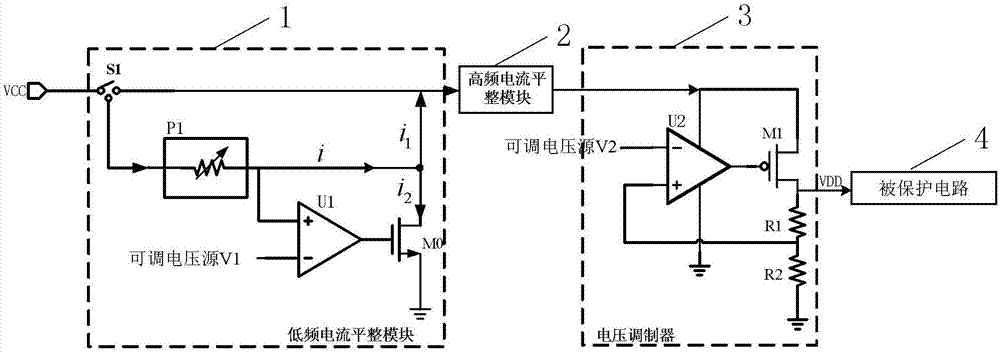
[0024] Specific implementation mode one: see figure 1 Describe this embodiment, a password protection circuit for defending against energy consumption attacks described in this embodiment, which includes a low-frequency current leveling module 1, a high-frequency current leveling module 2, and a voltage modulator 3;
[0025] The low-frequency current leveling module 1 is used to generate a constant target leveling current i, and use the constant target leveling current i to affect the load current i 1 to be compensated, the load current i 1 Used to provide electric energy to the protected circuit 4; wherein, i=i 1 + i 2 , i 2 is the compensation current;
[0026] The low-frequency current leveling module 1 is also used for high-frequency filtering of the voltage output by the power supply VCC;
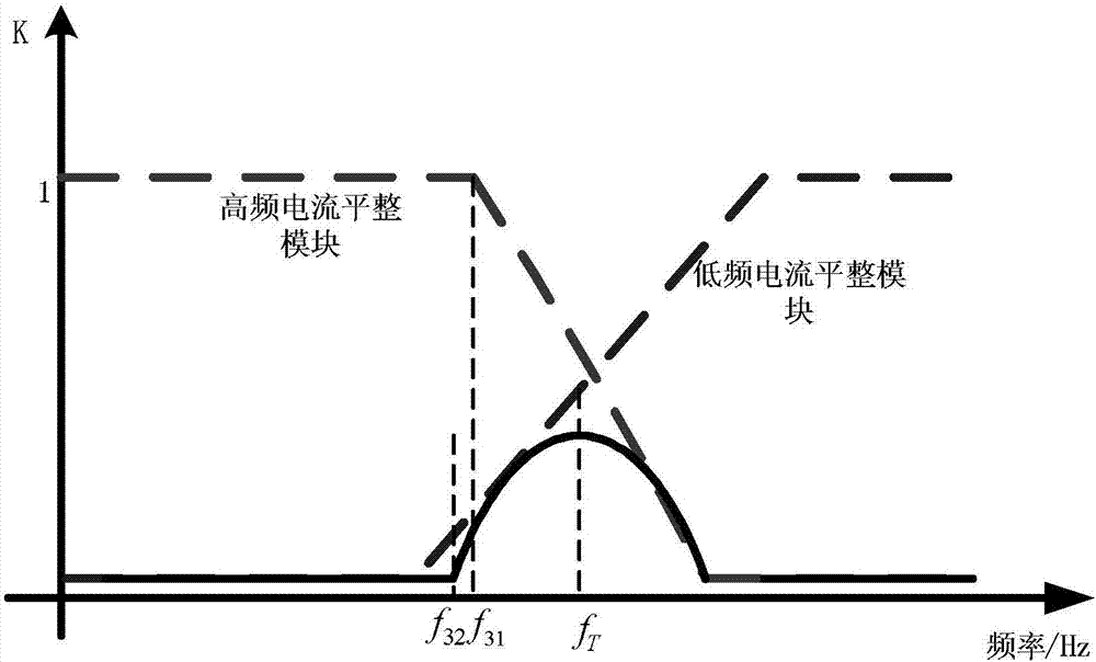
[0027] The high-frequency current leveling module 2 is used for the load current i output by the low-frequency current leveling module 1 1 Perform low-frequency filtering, and co...
specific Embodiment approach 2
[0032] Specific implementation mode two: see figure 1 Describe this embodiment. The difference between this embodiment and the password protection circuit for defending against energy consumption attacks described in Embodiment 1 is that the low-frequency current leveling module 1 includes a single-pole double-throw switch S1, a target current gear Bit setting circuit P1, amplifier U1 and N-type MOS transistor;
[0033] The control terminal of the SPDT switch S1 is connected to the voltage output terminal of the power supply VCC, the No. 1 output terminal of the SPDT switch S1 is connected to the current input terminal of the high-frequency current leveling module 2, and the No. 2 output terminal of the SPDT switch S1 The output terminal is connected to the electrical signal input terminal of the target current gear setting circuit P1, the target current output terminal of the target current gear setting circuit P1 is connected to the non-inverting input terminal of the amplif...
specific Embodiment approach 3
[0036] Specific implementation mode three: see figure 1 Describe this embodiment. The difference between this embodiment and the password protection circuit for defending against energy consumption attacks described in Embodiment 1 or Embodiment 2 is that the voltage modulator 3 includes an amplifier U2, a resistor R1, and a resistor R2 and P-type MOS transistor M1;
[0037] The inverting input terminal of the amplifier U2 is used to access the adjustable voltage source V2, the same input of the amplifier U2 is connected to one end of the resistor R1 and one end of the resistor R2 at the same time, the other end of the resistor R2 is connected to the power ground, and the resistor R1 The other end is connected to the drain of the P-type MOS transistor M1, and the other end of the resistor R1 is used as the voltage output end of the voltage modulator 3;
[0038] The power input terminal of the amplifier U2 is connected to the voltage output terminal of the high-frequency curre...
PUM
 Abstract
Description
Claims
Application Information
 - R&D
- Intellectual Property
- Life Sciences
- Materials
- Tech Scout
- Unparalleled Data Quality
- Higher Quality Content
- 60% Fewer Hallucinations
Browse by: Latest US Patents, China's latest patents, Technical Efficacy Thesaurus, Application Domain, Technology Topic, Popular Technical Reports.
© 2025 PatSnap. All rights reserved.Legal|Privacy policy|Modern Slavery Act Transparency Statement|Sitemap|About US| Contact US: help@patsnap.com