Solid-liquid hybrid rocket combined cycle propelling system and control method thereof

A solid-liquid mixing and propulsion system technology, applied in jet propulsion devices, rocket engine devices, machines/engines, etc., can solve the problems of difficult propellant development and ignition, inaccurate gas flow adjustment, complex system structure, etc. The effect of multiple starts, avoiding unstable combustion, and simple system structure layout

Inactive Publication Date: 2017-12-22
BEIHANG UNIV
View PDF5 Cites 21 Cited by
  • Summary
  • Abstract
  • Description
  • Claims
  • Application Information

AI Technical Summary

Problems solved by technology

[0004] The purpose of the present invention is to provide a solid-liquid hybrid rocket combined cycle propulsion system and its control method, to solve the problem of complex structure, unstable co

Method used


Image

  • Solid-liquid hybrid rocket combined cycle propelling system and control method thereof
  • Solid-liquid hybrid rocket combined cycle propelling system and control method thereof
  • Solid-liquid hybrid rocket combined cycle propelling system and control method thereof

Examples


specific Embodiment 1

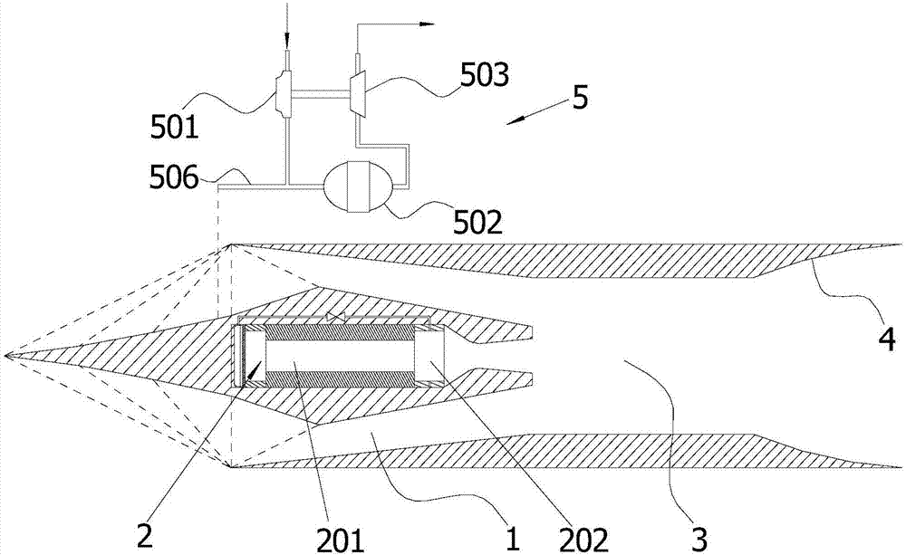
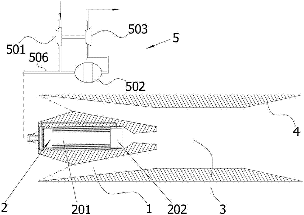
[0041] This embodiment provides a solid-liquid hybrid rocket combined cycle propulsion system, wherein: figure 1 It is a schematic structural diagram of the solid-liquid hybrid rocket combined cycle propulsion system provided by Embodiment 1 of the present invention. Such as figure 1 As shown, the solid-liquid hybrid rocket combined cycle propulsion system includes an air inlet 1 , a solid-liquid hybrid rocket engine 2 , a superchamber 3 , a tail nozzle 4 and an oxidizer delivery device 5 . Specifically, the solid-liquid hybrid rocket engine 2, the superchamber 3 and the tail nozzle 4 are communicated successively. Wherein, a combustion chamber 201 and a supplementary combustion chamber 202 are successively arranged in the solid-liquid hybrid rocket engine 2 . The air inlet 1 is arranged on the circumferential outer side of the solid-liquid hybrid rocket engine 2 and directly communicates with the superchamber 3 . In addition, the oxidant delivery device 5 is respectively c...

specific Embodiment 2

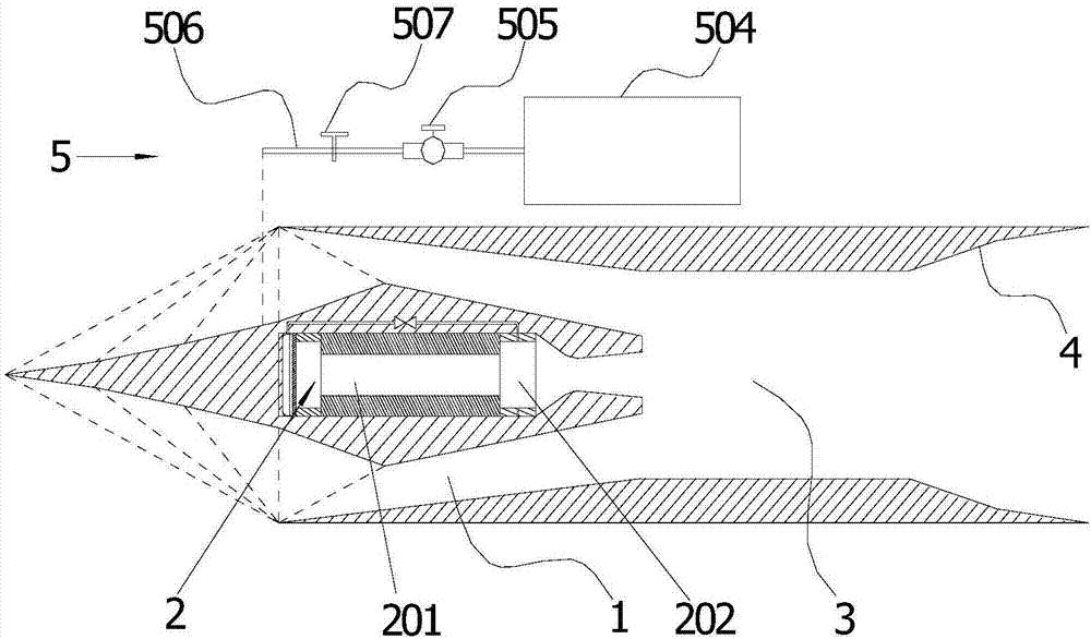
[0045] Such as figure 1 As shown, the solid-liquid hybrid rocket combined cycle propulsion system includes an air inlet 1 , a solid-liquid hybrid rocket engine 2 , a superchamber 3 , a tail nozzle 4 and an oxidizer delivery device 5 . Specifically, the solid-liquid hybrid rocket engine 2, the superchamber 3 and the tail nozzle 4 are communicated successively. Wherein, a combustion chamber 201 and a supplementary combustion chamber 202 are successively arranged in the solid-liquid hybrid rocket engine 2 . The air inlet 1 is arranged on the circumferential outer side of the solid-liquid hybrid rocket engine 2 and directly communicates with the superchamber 3 . In addition, the oxidant delivery device 5 is respectively connected to the combustion chamber 201 and the afterburner chamber 202 .

[0046] image 3 It is a schematic structural diagram of the solid-liquid hybrid rocket combined cycle propulsion system provided by Embodiment 2 of the present invention. Optionally, as...


PUM


Abstract

The invention provides a solid-liquid hybrid rocket combined cycle propelling system, and relates to the technical field of aerospace power equipment. The solid-liquid hybrid rocket combined cycle propelling system comprises an air inlet, a solid-liquid hybrid rocket engine, a super combustion chamber, an exhaust nozzle and an oxidizing agent conveying device. The solid-liquid hybrid rocket engine, the super combustion chamber and the exhaust nozzle are successively communicated in sequence. A combustion chamber and an after-combustion chamber are successively arranged in the solid-liquid hybrid rocket engine. The air inlet is arranged on the circumferential outer side of the solid-liquid hybrid rocket engine and directly communicates with the super combustion chamber. The oxidizing agent conveying device is connected with the combustion chamber and the after-combustion chamber. The solid-liquid hybrid rocket combined cycle propelling system is simple in structure, safe, efficient and stable in combustion, ignition is easy, and the flow of an oxidizing agent and the thrust of the system can be flexibly adjusted. On the basis, the invention further provides a control method of the propelling system.

Description

technical field [0001] The invention relates to the technical field of aerospace power equipment, in particular to a solid-liquid hybrid rocket combined cycle propulsion system and a control method thereof. Background technique [0002] Combined cycle power technology can organically combine two or more power types, so that the power units can be integrated and their functions complement each other, and the most efficient power propulsion method can be adopted for different flight stages of the aircraft to maximize The advantages of different power types can be brought into full play, thereby greatly expanding the altitude-speed envelope of the aircraft. At present, combined power technology is usually an organic combination of liquid rocket engine, turbine engine and other technologies and ramjet technology. The main types are: rocket-based combined cycle power, turbine-based combined cycle power, pre-cooling combined cycle power, etc. [0003] The existing rocket-based co...

Claims


Application Information

Patent Timeline
IPC IPC(8): F02K9/72F02K9/82
CPCF02K9/72F02K9/82
Inventor 俞南嘉张源俊李承恩何凌飞于瑞鹏
Owner BEIHANG UNIV
Why Eureka
Try Eureka