Unit-motor modularized permanent magnetism synchronous linear motor

A permanent magnet synchronous linear and motor module technology, used in electromechanical devices, electrical components, electric components, etc., can solve the problems of large thrust fluctuations of permanent magnet synchronous linear motors, suppress end effects, reduce volume and mass, and improve The effect of thrust density

Active Publication Date: 2017-12-22
江苏凌差智驱电气装备有限责任公司
View PDF6 Cites 8 Cited by
  • Summary
  • Abstract
  • Description
  • Claims
  • Application Information

AI Technical Summary

Problems solved by technology

[0003] In order to solve the problem of large thrust fluctuation of existing permanent magnet synchronous l

Method used


Image

  • Unit-motor modularized permanent magnetism synchronous linear motor
  • Unit-motor modularized permanent magnetism synchronous linear motor
  • Unit-motor modularized permanent magnetism synchronous linear motor

Examples


Embodiment approach 1

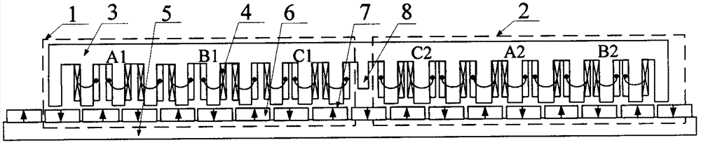
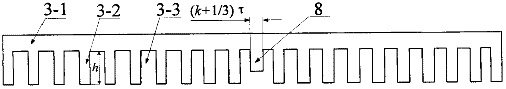
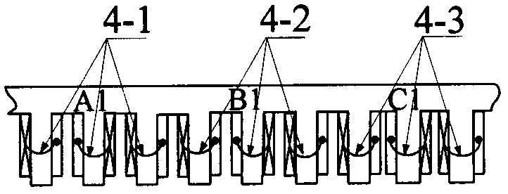
[0022] Such as figure 1 , as shown in 2, 3, 4, 5, the unit motor modular permanent magnet synchronous linear motor includes unit motor one 1 and unit motor two 2, and each unit motor includes a primary component and a secondary component. The primary assembly is composed of a primary iron core 3 and an armature winding 4. A slot 3-3 is formed on the primary iron core 3 to form a primary yoke 3-1 and a primary tooth 3-2 structure, and the armature winding 4 is arranged in the slot 3-3. The secondary assembly consists of a secondary core 5 and a permanent magnet 6 . There is an air gap 7 between the primary and secondary components. A magnetic modulation structure 8 is arranged between the unit motor 1 and the unit motor 2 . The magnetic modulation structure 8 is made of a magnetically permeable material and integrated with the primary iron core 3 . On the magnetic adjustment structure 8, the width of the magnetic adjustment yoke portion 8-1 is S=(k+1 / 3)τ (k is an integer, and...

Embodiment approach 2

[0026] Such as Figure 6 As shown, the motor adopts three unit motor structures, a magnetic modulation structure 12 is set between the first unit motor 9 and the second unit motor 10, and a magnetic modulation structure 13 is set between the second unit motor 10 and the third unit motor 11. The phase sequence of the windings on unit motor one 9 is set according to phase A winding-phase B winding-phase C winding. The phase sequence of the windings on the unit motor 2 10 is set according to phase C winding-phase A winding-phase B winding. The phase sequence of the windings on the unit motor three 11 is set according to B-phase winding-C-phase winding-A-phase winding. On any two adjacent unit motors, the winding directions of the same-phase windings are opposite.


PUM


Abstract

The invention provides a unit-motor modularized permanent magnetism synchronous linear motor, and belongs to the technical field of a motor. The unit-motor modularized permanent magnetism synchronous linear motor is formed by a plurality of unit motors, wherein each unit motor includes a primary assembly and a secondary assembly, wherein the primary assembly is formed by a primary iron core and armature windings; grooves are formed in the primary iron core, and the armature windings are arranged in the grooves; the secondary assembly is formed by a permanent magnet and a secondary iron core; an air gap is located between the primary assembly and the secondary assembly; a magnetic modulation structure is arranged between two adjacent unit motors; the width of the magnetic modulation structure is that S=(k+1/3)Tau (k is an integer and Tau is the polar distance of the motor); the arranging sequences of the windings in the grooves of two adjacent unit motors are different; and the winding directions of the windings on the two unit motors are opposite. The structure is conductive to inhibition of end portion effect, and can improve asymmetry of three-phase windings of the permanent magnetism synchronous linear motor and reduce thrust ripple.

Description

technical field [0001] The invention belongs to the field of motors, in particular to a modularized permanent magnet synchronous linear motor of a unit motor. Background technique [0002] The direct transmission technology based on linear motors eliminates the need for intermediate complex transmission mechanisms. It has been applied in linear motion occasions such as machine tools and elevators, and its application fields are gradually expanding to various fields of production and life. The permanent magnet synchronous linear motor has the advantages of simple and reliable structure, high thrust and thrust density, so it has broad application prospects in various high-precision linear motion control occasions. Different from the rotating motor, the iron core of the linear motor has an end, and the end effect causes the harmonic component of the magnetic field to increase, causing the positioning force and thrust fluctuation to increase. Therefore, reducing the positioning ...

Claims


Application Information

Patent Timeline
IPC IPC(8): H02K41/03H02K3/28
Inventor 黄旭珍嵇天鹏李静
Owner 江苏凌差智驱电气装备有限责任公司
Why Eureka
Try Eureka