Batch-type electrodeposition core-shell-type powder electroplating device and treatment method thereof
An electroplating device and electrodeposition technology, which is applied to electrodes, plating tanks, electrolysis processes, etc., can solve the problems that powder electroplating devices cannot be applied to nano-scale to sub-millimeter-sized powders, and the uniformity of the coating layer is not ideal. The effect of large-scale production, controllable coating thickness and low cost
- Summary
- Abstract
- Description
- Claims
- Application Information
AI Technical Summary
Problems solved by technology
Method used
Image

Examples
Embodiment 1
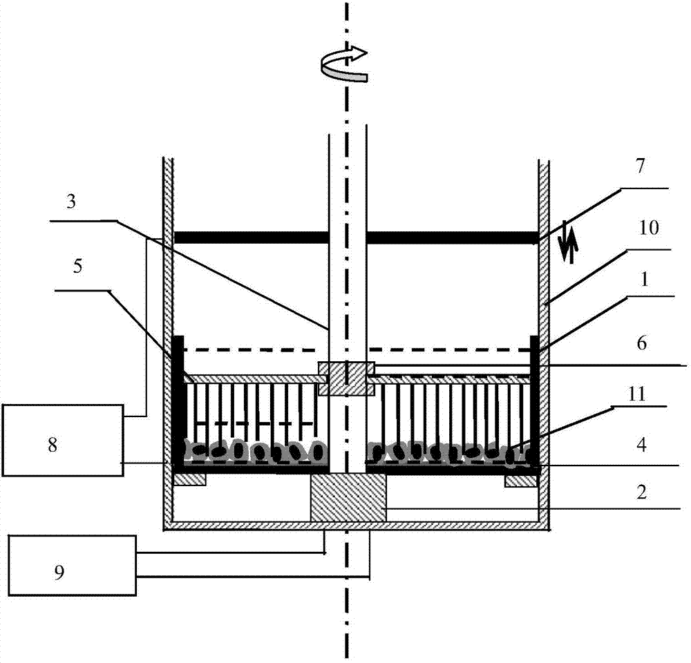
[0057] This embodiment provides a batch type electrodeposition core-shell type powder electroplating device, such as figure 1 As shown, the electroplating device includes an electroplating tank 1, a motor 2, a motor transmission shaft 3, a cathode plate 4, a stirring structure 5, a clamping structure 6, an anode plate 7 and a power supply 8;
[0058] Wherein, the motor 2 is located in the middle of the bottom outside the electroplating tank 1, the motor transmission shaft 3 is arranged on the motor 2, the motor transmission shaft 3 runs through the electroplating tank 1, the cathode plate 4 is laid in the electroplating tank 1, and the stirring structure 5 is fixed by the clamping structure 6 On the motor transmission shaft 3 and placed in the electroplating tank 1, the anode plate 7 is fixed on the motor transmission shaft 3 and moves up and down along the motor transmission shaft 3, the anode plate 7 is located above the electroplating tank 1, the power supply 8 is connected ...
Embodiment 2
[0064] This embodiment provides an intermittent electrodeposition core-shell powder electroplating device, the structure of which is the same as that of the device described in Embodiment 1, the difference is that the material of the anode plate 7 is a Sn-Ag alloy, and the cathode plate 4 is Made of stainless steel.
Embodiment 3
[0066] This embodiment provides an intermittent electrodeposition core-shell powder electroplating device, the structure of which is the same as that of the device described in Embodiment 1, the difference is that the material of the anode plate 7 is Fe-Ni alloy, and the cathode plate 4 is Metallic copper material.
PUM
 Abstract
Description
Claims
Application Information
 - Generate Ideas
- Intellectual Property
- Life Sciences
- Materials
- Tech Scout
- Unparalleled Data Quality
- Higher Quality Content
- 60% Fewer Hallucinations
Browse by: Latest US Patents, China's latest patents, Technical Efficacy Thesaurus, Application Domain, Technology Topic, Popular Technical Reports.
© 2025 PatSnap. All rights reserved.Legal|Privacy policy|Modern Slavery Act Transparency Statement|Sitemap|About US| Contact US: help@patsnap.com