Conveying device with loading and unloading device and luggage conveying vehicle

A loading and unloading device and transmission device technology, which is applied in the field of luggage transfer vehicles, can solve the problems of shoulder, waist, and leg injuries of workers, luggage rolling down, and low transition efficiency, so as to improve the stability of luggage and shorten the length of the vehicle , the effect of reducing labor intensity

Inactive Publication Date: 2017-12-29
XIAMEN UNIV OF TECH +1
View PDF10 Cites 4 Cited by
  • Summary
  • Abstract
  • Description
  • Claims
  • Application Information

AI Technical Summary

Problems solved by technology

[0004] 1. In order to prevent the baggage from rolling down during the conveying process due to the excessive inclination angle of the conveying frame, the luggage conveying vehicle is often designed to have a long vehicle length. Generally, the entire baggage conveying vehicle is as long as 11 meters. Due to the excessive length of the conveying vehicle , the turning radius is too large, the maneuverability is poor during operation, the transition efficiency is low, and there are great safety hazards;
[0005] 2. Due

Method used


Image

  • Conveying device with loading and unloading device and luggage conveying vehicle
  • Conveying device with loading and unloading device and luggage conveying vehicle
  • Conveying device with loading and unloading device and luggage conveying vehicle

Examples


Embodiment 1

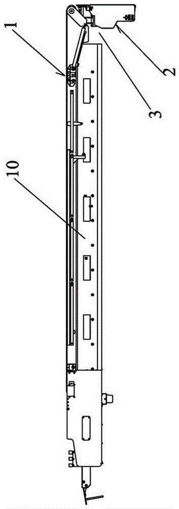
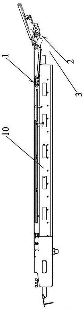
[0035] What the present invention discloses is a kind of conveying device with loading and unloading device, such as figure 1 As shown, it is a preferred embodiment of the present invention. The conveying device is composed of a main conveying device 1 and a loading and unloading device 2 that can be hidden and movably installed at the lower end of the main conveying device 1. Specifically, the loading and unloading device 2 can be pushed and pulled to be hidden in the main conveying device 1. It is hidden under or folded under the main conveying device 1. When luggage conveying is required, the loading and unloading device 2 is pulled out or flipped out, such as figure 2 As shown, on the one hand, the loading stroke of the main conveying device 1 can be extended, and on the other hand, the height of the end of the loading and unloading device 2 can be adjusted so that it can have a better docking with the luggage transfer workshop.

[0036] Among them, such as figure 1 and ...

Embodiment 2

[0041] Such as Figure 10 As shown, a baggage transfer vehicle includes a vehicle and a transfer device with a loading and unloading device as described in Embodiment 1 installed on the vehicle. 1. The loading and unloading device at the lower end is composed of 2. In order to solve environmental problems such as exhaust pollution and noise pollution caused by diesel power, and to avoid the impact of vibration on the stability of the luggage delivery vehicle during engine operation, this embodiment uses an electric vehicle as the main body of the vehicle. Electric automobile comprises headstock 93 and the automobile chassis 94 that is positioned at the headstock rear, and the electric driving device 95 that drives car ahead is fixedly installed on the both sides tops of automobile chassis 94. The lower end of the transmission device is rotatably connected in the middle of the car chassis 94 afterbody, and the main lifting mechanism that can control the lifting of the transmiss...


PUM


Abstract

The invention discloses a conveying device with a loading and unloading device. The conveying device is composed of a main conveying device and the loading and unloading device which is movably installed at the lower end of the main conveying device in a hidden manner, a lifting mechanism capable of changing the height of the other end of the loading and unloading device is arranged between a main conveyer belt and the first end of the loading and unloading device, and the loading and unloading device achieves telescopic operation of the conveyer belt by assembling a belt telescoping structure. According to the conveying device, the aligning precision of luggage loading points and unloading points can be improved, the labor intensity in the luggage stacking process is greatly reduced, the operation efficiency is improved, and occupational diseases of workers are reduced; meanwhile, the vehicle length can be decreased as much as possible when a luggage conveying vehicle is designed, and then the transition flexibility of the luggage conveying vehicle can be improved.

Description

technical field [0001] The invention relates to the field of article conveying and transportation, in particular to a conveying device provided with a loading and unloading device and a baggage conveying vehicle provided with the conveying device. Background technique [0002] At present, with the rapid development of my country's aviation industry, the number of airports in my country is also increasing rapidly. At the same time, the continuous increase of bulk cargo transportation in many airports makes the demand for luggage delivery vehicles in various airports more and more. Patent ZL200710047377.2 discloses the basic structure of the existing baggage transfer vehicle in my country. The baggage transfer vehicle is generally composed of a body and a liftable transfer frame installed on the body. The transfer frame is jointly driven by the hydraulic system and the electrical system to realize the connection between the aircraft in the airport and the ground. transfer of lu...

Claims


Application Information

Patent Timeline
IPC IPC(8): B65G21/14B65G23/44B65G47/51B64F1/32
CPCB64F1/32B65G21/14B65G23/44B65G47/5104
Inventor 欧阳联格韩锋钢朱世开徐永明戚玉柱
Owner XIAMEN UNIV OF TECH
Why Eureka
Try Eureka