
Plasma auxiliary-heating melting and gasifying reactor

An auxiliary heating, melting and gasification technology, applied in gasification process, manufacture of combustible gas, petroleum industry, etc., can solve the problems of equipment cost increase, extremely high power, uneven distribution of temperature field, etc., to avoid pyrolysis gasification, Increased service life and reduced power consumption

Active Publication Date: 2015-03-25
中国东方电气集团有限公司
View PDF10 Cites 19 Cited by
  • Summary
  • Abstract
  • Description
  • Claims
  • Application Information

AI Technical Summary

Problems solved by technology

[0006] However, the current plasma waste gasification technology still has many deficiencies.
First of all, direct gasification of garbage with a plasma torch requires a huge amount of power, and its power consumption rate can reach 30% to 40% of the power it produces. Due to the high power consumption, the operating cost is greatly increased, making it unworthy of commercial operation
Second, this method gasifies garbage, and a dioxin treatment device needs to be added to the subsequent gas purification process, which increases the initial one-time investment and greatly increases the equipment cost
Third, using a plasma torch to directly gasify garbage, due to the uneven distribution of its temperature field, the garbage cannot be completely treated at high temperature, and there will be a large amount of dioxins and other harmful substances in the discharged waste residue, which makes the treatment of its waste residue become a problem. a problem

Method used


Image

  • Plasma auxiliary-heating melting and gasifying reactor

Examples


Embodiment Construction

[0028] Below in conjunction with accompanying drawing and specific embodiment the present invention is described in further detail:

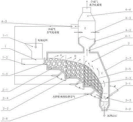
[0029] Such as figure 1 As shown, a plasma-assisted heating melting gasification reactor for converting municipal solid waste into synthesis gas and inert slag products according to the present invention includes a feeder 1, a reaction chamber 2, and a gasification reaction chamber Chamber furnace wall 2-7, the feeder 1 is connected with the reaction chamber 2, and the reaction chamber 2 sequentially includes a drying area A with an additional circulating thermal synthesis gas along the horizontal direction according to the reaction sequence, and a drying area with an additional circulating thermal synthesis gas. And the pyrolysis and gasification zone B with steam added, the burnout zone C with heated air, the ash melting zone D with a plasma generator, and the drying zone A through the feed port 1-1 of the reaction furnace and the feed materia...


PUM


Abstract

The invention relates to a plasma auxiliary-heating melting and gasifying reactor. The plasma auxiliary-heating melting and gasifying reactor comprises a feeder and a reaction chamber, wherein the feeder is connected with the reaction chamber; the reaction chamber sequentially comprises a drying area, a pyrolysis and gasification area, a burn-out area and an ash melting area according to a reaction sequence along a horizontal direction; the drying area is connected with the feeder through a charge port; the bottom of the pyrolysis and gasification area is lower than that of the drying area; the bottom of the burn-out area is lower than that of the pyrolysis and gasification area; the bottom of the ash melting area is lower than that of the burn-out area; the top of the burn-out area is connected with a synthesis gas reforming area through a throat opening; plasma torches are arranged in both the ash melting area and the synthesis gas reforming area. According to the plasma auxiliary-heating melting and gasifying reactor disclosed by the invention, the plasma torches are used as a high-quality external heat source for melting the ash generated after pyrolysis and gasification for household garbage, and the gasified synthesis gas is reformed, thus removing all harmful substances which are possibly generated by the household garbage in pyrolysis and gasification processes, reducing the one-time investment cost and operation cost of garbage plasma gasification, and enabling the synthesis gas to be purer.

Description

technical field [0001] The invention relates to the treatment technology of solid waste mainly including urban living garbage, in particular to a plasma-assisted heating melting gasification reactor capable of preventing dioxin from being produced. Background technique [0002] With the continuous growth of the global economy and the acceleration of urbanization, the generation of domestic waste has become an increasingly serious environmental problem. The increasing output of municipal solid waste and its environmental pollution has become a common problem faced by all countries. Harmless treatment of municipal solid waste is one of the important measures to promote the sustainable development of economy and ecological environment. [0003] At present, the harmless treatment technologies of municipal solid waste include composting technology, landfill technology, incineration technology and gasification technology. Neither landfill nor compost can fully realize the harmles...

Claims


Application Information

Patent Timeline
Patent Type & Authority Applications(China)
IPC IPC(8): C10J3/60C10J3/82C10J3/72
CPCC10J3/66C10J3/82C10J2300/0946C10J2300/0956C10J2300/1238C10J2300/1246C10J2300/1618C10J2300/1823
Inventor 张春飞王希谢斐李宏王晓亮
Owner 中国东方电气集团有限公司
Learn More