Remote signal transmission system based on optical fiber

A transmission system and remote signal technology, applied in optical fiber transmission, transmission system, electromagnetic wave transmission system, etc., can solve the problems of low gain coefficient, low pump efficiency, high pump power, etc., and achieve high gain coefficient and low pump power , The effect of high pump efficiency

Inactive Publication Date: 2017-12-29
成都驹月科技有限公司
View PDF5 Cites 2 Cited by
  • Summary
  • Abstract
  • Description
  • Claims
  • Application Information

AI Technical Summary

Problems solved by technology

[0003] However, in the current optical fiber communication system, Raman amplification is generally used for optical signal amplification. Due to the low gain coefficient of Raman amplification, low pumping efficiency, and high pumping power, the optical fiber connector and optoelectronic devices are easily burned out, and the cost is expensive. , in summary, it is not suitable for LAN optical fiber communication or small-scale optical fiber communication system

Method used


Image

  • Remote signal transmission system based on optical fiber

Examples


Embodiment Construction

[0014] In order to make the purpose, technical solutions and advantages of the present invention clearer, the present invention will be further described in detail below in conjunction with the examples and accompanying drawings. As a limitation of the present invention.

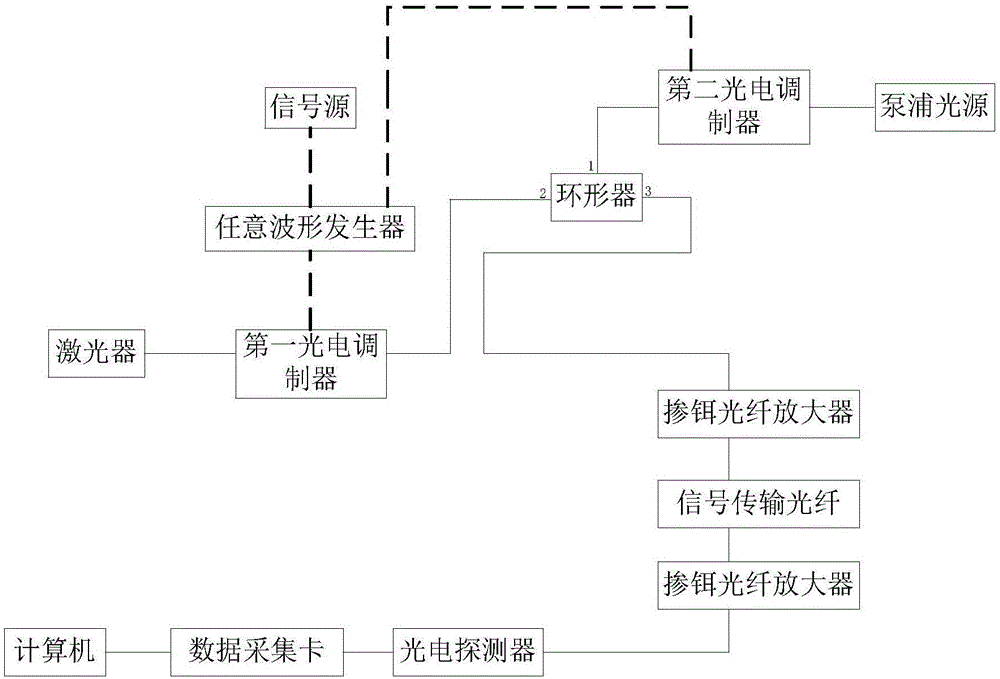
[0015] Such as figure 1 As shown, a remote signal transmission system based on optical fiber, the solid line in the figure represents the optical fiber, and the dotted line represents the electrical signal control circuit; the present invention includes an optical fiber, a laser, a first photoelectric modulator, a circulator, a second photoelectric modulator, a pump Pu light source, signal transmission fiber, photoelectric detector, data acquisition card and computer; the laser adopts semiconductor laser, the optical fiber and signal transmission fiber adopt polarization-maintaining multimode fiber, the outer surface of the signal transmission fiber has a toughened cladding, and the output of the laser The ...


PUM


Abstract

The present invention discloses a remote signal transmission system based on an optical fiber, and mainly relates to optical communication. The system comprises an optical fiber, a laser, a signal source, an arbitrary waveform generator, a first electrooptic modulator, a circulator, a second electrooptic modulator, a pump light source, a signal transmission optical fiber, an erbium-doped fiber amplifier, a photoelectric detector, a data collection card and a computer. The signal source controls the first electrooptic modulator through the arbitrary waveform generator to load electric signals to be transmitted on a laser, and the arbitrary waveform generator modulates the pump amplification light frequency of the pump light source and the emergent light frequency of the first electrooptic modulator to one Brillouin frequency shift so as to realize Brillouin amplification of the emergent light of the first electrooptic modulator. The amplification mechanism is high in gain coefficient, high in pump efficiency and low in required pump efficiency.

Description

technical field [0001] The invention relates to optical communication, in particular to an optical fiber-based remote signal transmission system. Background technique [0002] Standing out from optical communication, optical fiber communication technology has become one of the main pillars of modern communication and plays a pivotal role in modern telecommunication networks. As an emerging technology, optical fiber communication has been developing rapidly and widely used in recent years, which is rare in the history of communication. It is also an important symbol of the world's new technology revolution and the main transmission tool for various information in the future information society. [0003] However, in the current optical fiber communication system, Raman amplification is generally used for optical signal amplification. Due to the low gain coefficient of Raman amplification, low pumping efficiency, and high pumping power, the optical fiber connector and optoelect...

Claims


Application Information

Patent Timeline
Patent Type & Authority Applications(China)
IPC IPC(8): H01S3/067H01S3/091H01S3/30H04B10/25H04B10/548H04B10/50
CPCH01S3/06708H01S3/06716H01S3/091H01S3/302H04B10/25891H04B10/505H04B10/548
Inventor 康宏昊
Owner 成都驹月科技有限公司
Why Eureka
Try Eureka