Cholera diagnosis microfluidic device with quickly dismountable sample liquid driving component

A technology of microfluidic device and microfluidic chip, which is applied in the field of analysis and testing, and can solve problems that have not been properly solved, such as large flow resistance and difficulty in the passage of fine liquid flow.

Inactive Publication Date: 2018-01-05
李榕生
View PDF1 Cites 0 Cited by
  • Summary
  • Abstract
  • Description
  • Claims
  • Application Information

AI Technical Summary

Problems solved by technology

[0007] But it's not that simple
[0008] First, this polydimethylsiloxane material, which is referred to by the acronym PDMS, is itself a strongly hydrophobic material, and channels are built on this material. modification operation, then, after the overall assembly is completed, that is, after the cover is covered, because the inner surface of the channel in the structure occupies most of the inner surface of the liquid flow channel, then the inner surface of the PDMS channel is The strong hydrophobicity is the decisive factor, it will make it very difficult for the polar liquid fine flow similar to the aqueous solution to pass through, and its flow resistance is so large that even the general micropump is difficult to push, of course, if the cover sheet is also If you choose to use the PDMS material, then the problems are basically the same, with minor differences; therefore, in the prior art, it is necessary to modify and modify the inner surface of the channel on the PDMS material; then, this is for the PDMS channel Is the modification operation of the inner surface of the channel very troublesome? That's not the problem. What constitutes a serious technical problem is an

Method used


Image

  • Cholera diagnosis microfluidic device with quickly dismountable sample liquid driving component
  • Cholera diagnosis microfluidic device with quickly dismountable sample liquid driving component
  • Cholera diagnosis microfluidic device with quickly dismountable sample liquid driving component

Examples


Embodiment Construction

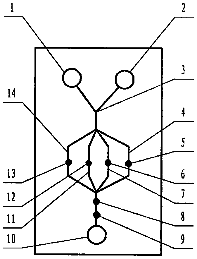
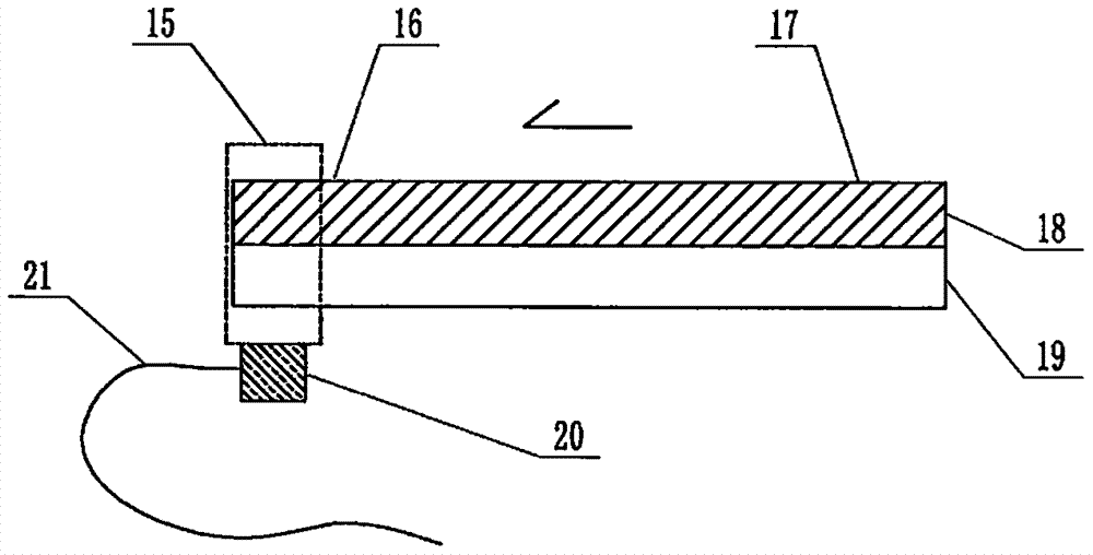
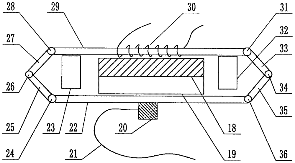
[0078] exist figure 1 , figure 2 and image 3In the shown embodiment of the present case, the structure of the microfluidic device includes a multi-channel microfluidic chip, and the structure of the microfluidic chip includes a substrate 18 and a cover sheet 19 that are attached to each other and installed together. Both the substrate 18 and the cover sheet 19 are plates or sheets, and the side of the substrate 18 facing the cover sheet 19 contains a channel structure formed by a molding process or an etching process, and the substrate 18 also contains The window structure connected to the channel structure and pierced through the substrate is formed through a molding process, an etching process or a simple punching process, and the substrate 18 and the cover 19 that are attached to each other are jointly constructed to contain A microfluidic chip with a pipe structure and a liquid pool structure connected thereto, the liquid pools are liquid pool 1, liquid pool 2, and liq...


PUM

PropertyMeasurementUnit
Particle sizeaaaaaaaaaa
Diameteraaaaaaaaaa
Lengthaaaaaaaaaa

Abstract

Belonging to the field of analytical test, the invention relates to a cholera diagnosis microfluidic device with a quickly dismountable sample liquid driving component. A series of problems exist in making substrates of microfluidic chips for cholera diagnosis from cheap and easily processable polydimethylsiloxane (PDMS). The invention has the key points that: the substrate is made of PDMS with anoriginal ecological surface, the pipeline of the chip is filled with doped micron-sized titanium dioxide particles; the surface super-hydrophilic properties of the titanium dioxide particles can be induced through visible light irradiation in advance; the super-hydrophilic gap set among the particles of the titanium dioxide particular filler substitutes and surpasses the originally strong hydrophobic pipeline, thereby achieving a constant and super-hydrophilic modification effect. At the same time, micropower ultrasonic wave is employed to induce the interfacial tension difference at the headand tail ends of the chip, thus guiding a sample liquid to flow along the pipeline to a terminal direction.

Description

technical field [0001] The invention relates to a microfluidic device for cholera diagnosis, which can quickly remove components for driving sample liquid, and belongs to the field of analysis and testing. Background technique [0002] For the technical background of multi-channel microfluidic cholera diagnosis, please refer to CN 200910150930.4 and other invention patent applications. [0003] As far as the overall overview of microfluidic technology itself is concerned, you can refer to the monograph "Illustrated Microfluidic Chip Laboratory" published by the famous microfluidic expert Mr. Lin Bingcheng not long ago, which has been published by Science Press. The past, present, and future prospects of microfluidic technology, etc., have detailed and long-form discussions that go deep into specific details. [0004] So, let's talk about the key issues of this case. [0005] The basic structure of a microfluidic chip includes a substrate etched with channels and a cover sh...

Claims


Application Information

Patent Timeline
IPC IPC(8): B01L3/00G01N27/26G01N33/569
CPCY02A50/30
Inventor 李榕生
Owner 李榕生
Why Eureka
Try Eureka