Station self-control dust removal system

A dust removal system and station technology, applied in the direction of dust removal, cleaning methods and tools, chemical instruments and methods, etc., can solve the problems of unbalanced dust dissipation, high operating power, and affecting workers' vision, and meet the needs of dust control , meet the needs of dust removal, good installation flexibility

Inactive Publication Date: 2018-01-09
LIAONING TECHNICAL UNIVERSITY
View PDF7 Cites 3 Cited by
  • Summary
  • Abstract
  • Description
  • Claims
  • Application Information

AI Technical Summary

Problems solved by technology

[0002] At present, in metallurgical forging, mechanical processing, light industrial production and other industries, it is common to encounter different degrees of dust pollution during the production stage, and the dust generated during the production stage will directly threaten human health. When the dust falls into the rotating parts of the production equipment On the other hand, it will accelerate the wear of rotating parts, thereby reducing the operating accuracy and service life of production equipment
In addition, when the dust permeates the production workshop, it will first reduce the visibility, which will not only affect the workers' vision, but also hinder the workers' operation, thereby reducing labor productivity, and even lead to safety accidents in severe cases.
[0003] Therefore, in order to avoid a series of disadvantages caused by dust pollution, manufacturers generally configure corresponding dust removal systems for production workshops. According to different dust removal principles, the

Method used


Image

  • Station self-control dust removal system
  • Station self-control dust removal system
  • Station self-control dust removal system

Examples


Embodiment Construction

[0017] The present invention will be further described in detail below in conjunction with the accompanying drawings and specific embodiments.

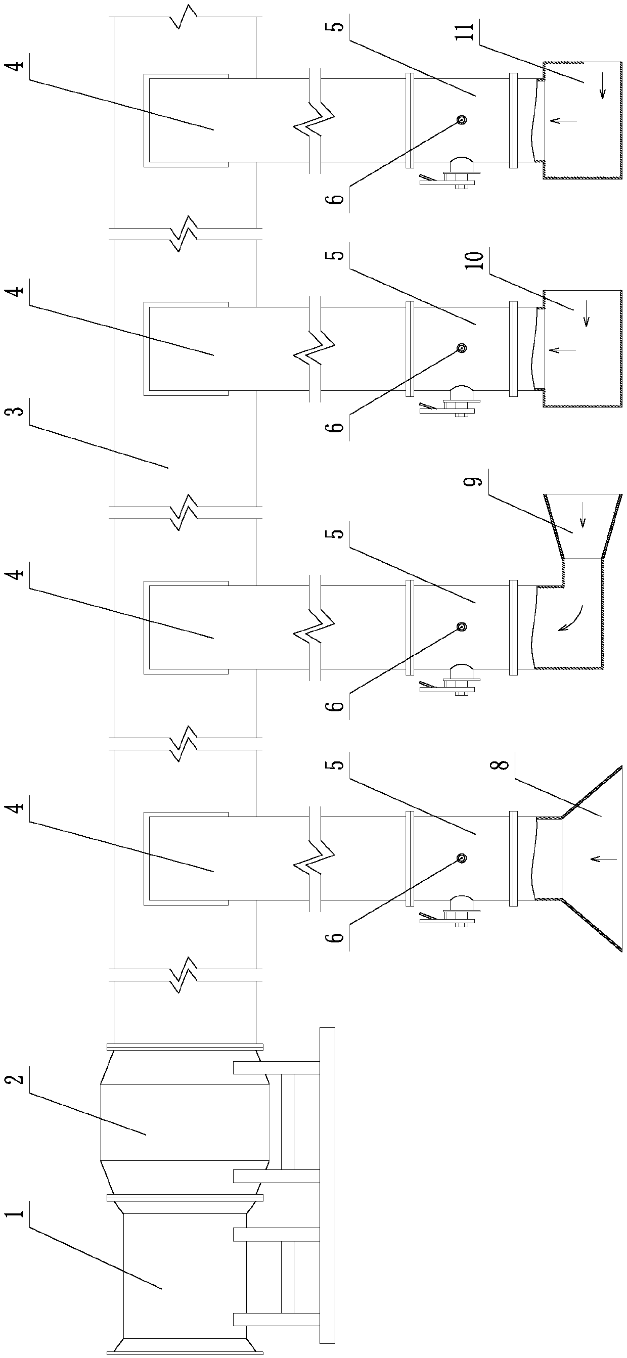
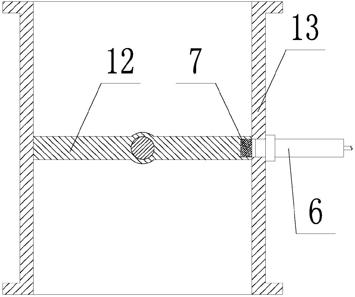
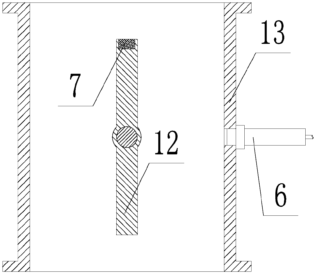
[0018] Such as Figure 1~3 As shown, a station self-control dust removal system includes a fan 1, a dust collector 2, a main ventilation pipeline 3, a branch ventilation pipeline 4, an exhaust hood, a damper 5, a Hall switch 6 and a magnet 7; The air suction port of fan 1 is connected with the outlet of dust remover 2, and the entrance of dust remover 2 is connected with main ventilation pipeline 3; A branch ventilation pipeline 4 is arranged between the stations, and an exhaust hood is installed at the end of each branch ventilation pipeline 4, and the air valve 5 is arranged at the end of the branch ventilation pipeline 4 and exhaust Between the air shields: the magnet 7 is fixedly installed on the valve plate 12 of the air valve 5, the Hall switch 6 is installed on the valve housing 13 of the air valve 5, and the Hall switch 6 coo...


PUM


Abstract

A station self-control dust removal system comprises a fan, a dust collector, a main vent line, branch vent lines, exhaust hoods, air valves, Hall switches and magnets; the dust collector is connectedbetween the fan and the main vent line, and one branch vent line is arranged between the main vent line and each station; the end of each branch vent line is provided with one exhaust hood, and the air valves are arranged between the ends of the branch vent lines and the exhaust hoods; the magnets are fixedly installed on valve plates of the air valves, and the Hall switches are installed on casings of the air valves, and matched with the magnets; when the air valves are closed, the magnets are adjacent and opposite to the Hall switches; when the air valves are opened, the magnets are separated from the Hall switches; the start-stop of the fan is controlled through a PLC; when the air valves of all stations are in the closed state, the fan is in a shutdown state; when the air valves of all the stations are in the open state, the fan runs with the maximum operating power; when the fan is started, the fan operating power is in direct proportion to the number of the air valves opened.

Description

technical field [0001] The invention belongs to the technical field of industrial dust removal equipment, in particular to a station self-control dust removal system. Background technique [0002] At present, in metallurgical forging, mechanical processing, light industrial production and other industries, it is common to encounter different degrees of dust pollution during the production stage, and the dust generated during the production stage will directly threaten human health. When the dust falls into the rotating parts of the production equipment On the other hand, it will accelerate the wear of rotating parts, thereby reducing the operating accuracy and service life of production equipment. In addition, when the dust permeates the production workshop, it will first reduce the visibility, which will not only affect the workers' vision, but also hinder the workers' operation, thereby reducing labor productivity, and even lead to safety accidents in severe cases. [000...

Claims


Application Information

Patent Timeline
IPC IPC(8): B08B15/00
Inventor 张一夫马丁翟巍王跃寰张振宇王洪铮
Owner LIAONING TECHNICAL UNIVERSITY
Why Eureka
Try Eureka