Alumina decomposition tank stirring system

A technology of a stirring system and a decomposition tank, which is applied in the field of dynamic stirring systems, can solve the problems of high maintenance and repair costs, high costs, and reduced reaction efficiency, and achieves the effects of low maintenance and maintenance costs, low manufacturing costs, and small effect.

Inactive Publication Date: 2018-01-09
广西信发铝电有限公司
View PDF5 Cites 3 Cited by
  • Summary
  • Abstract
  • Description
  • Claims
  • Application Information

AI Technical Summary

Problems solved by technology

Due to the huge size of the tank, a decomposition tank with a diameter of 14 meters and a height of 35 meters needs to be equipped with a 75-kilowatt stirring motor and gearbox, which is relatively expensive, not only consumes a lot of power, but also requires high maintenance and repair costs
In addition, the ordinary stirring decomposition process will cause the upper and lower liquids to mix with each other (commonly known as "short circuit"), reducing the supersaturation of the sodium aluminate solution that has just been transported to the decomposition tank, reducing the reaction efficiency, and at the same time strongly The full mixed flow agitation also caused the particle size of the crystallized product to decrease
[0004] The large-scale decomposition tank has a diameter of 14 meters and a height of 35 meters. The diameter of the upper stirring impeller is 8.4 meters, and the diameter of the bottom stirring impeller is 10 meters. The operating torque is very large. Strict requirements, complicated process and high production cost

Method used


Image

  • Alumina decomposition tank stirring system
  • Alumina decomposition tank stirring system

Examples


Embodiment Construction

[0021] The present invention will be further explained in detail below with reference to the drawings and specific embodiments of the specification. It is worth noting that the following specific embodiments are only used to illustrate the technical solutions of the present invention, rather than limiting, and are based on the spirit of the technical solutions of the present invention. Modification or equivalent replacement of the technical solution of the invention belongs to the protection scope of this patent right.

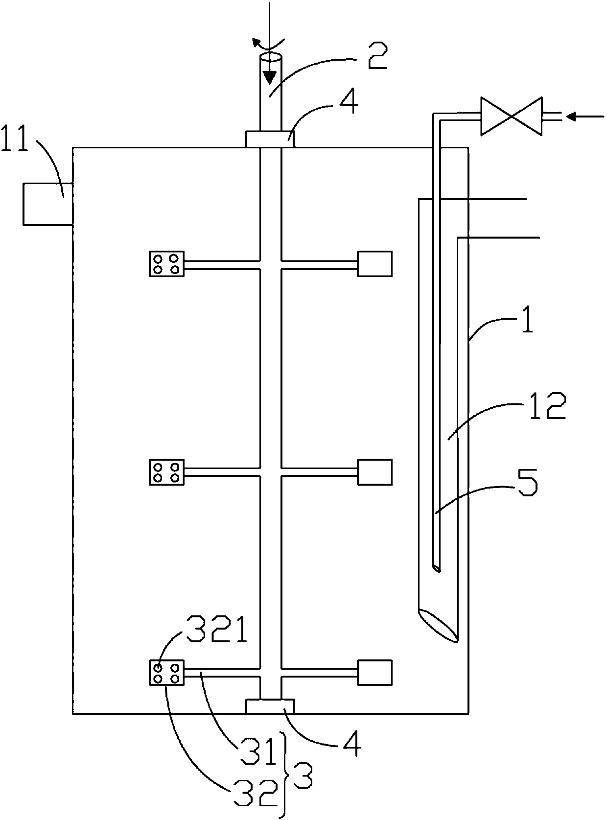
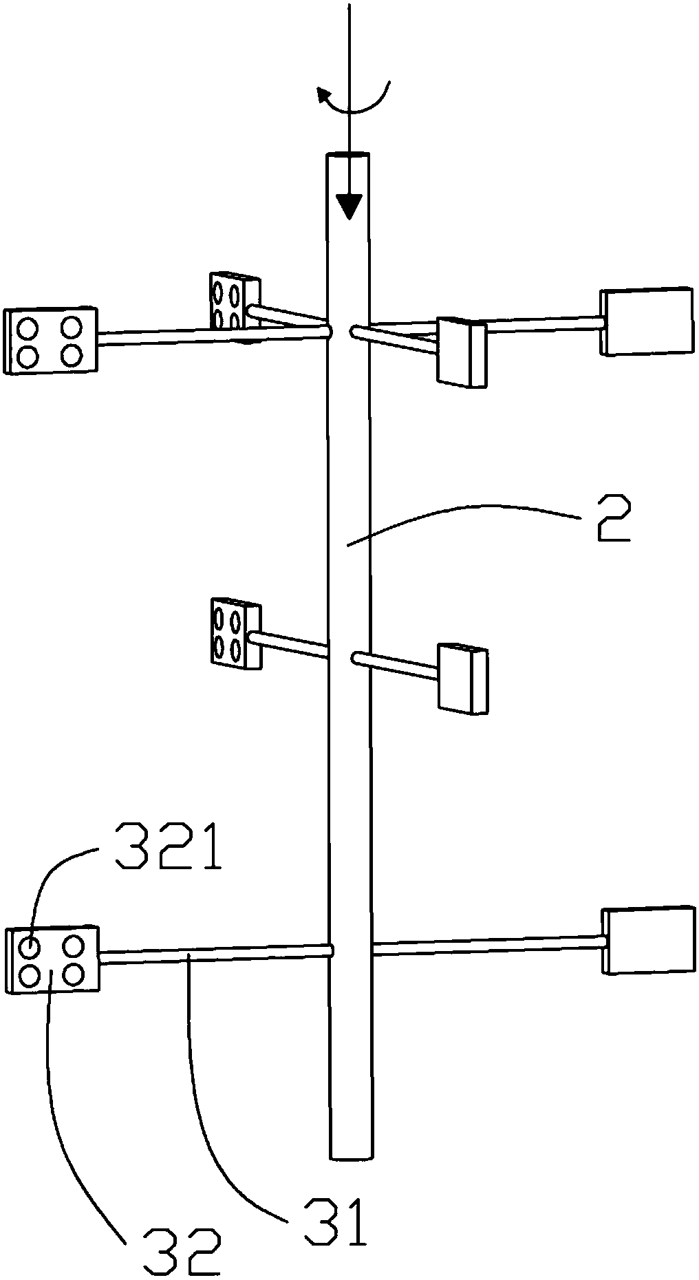
[0022] Such as figure 1 -2. An alumina decomposition tank stirring system, comprising a tank body 1 and a wind stirring device; the tank body 1 is a cylindrical structure, and the wind stirring device is used to stir the slurry inside the tank body 1; the tank body 1. A feeding pipe 11 is opened on the side of the tank 1 to feed the slurry into the cavity of the tank 1; from the upper side of the tank 1 a feeding pipe 12 extends directly to the bottom of the tank ...


PUM


Abstract

The invention discloses an alumina decomposition tank stirring system and belongs to the technical field of power stirring. The alumina decomposition tank stirring system comprises a tank body and a wind-driven stirring device, wherein the wind-driven stirring device comprises a ventilating shaft, a stirring blade and two bearings; the two bearings are respectively arranged on the top and at the bottom of the tank body and is used for supporting the ventilating shaft to rotate around the axis; one end of the ventilating shaft is opened, the other end of the ventilating shaft is provided with aclosed pipe fitting, and a side face of the ventilating shaft is connected with the stirring blade; the stirring blade comprises a blade and a ventilating pipe; the blade is of a flat cavity structure, a hole communicated with the cavity is formed in one surface of the blade, and the other opposite surface of the blade is used for driving and stirring slurry in the tank body; the ventilating pipeis used for fixedly connecting the blade and the ventilating shaft; and a pipe orifice of the ventilating shaft is communicated with the cavity of the blade. According to the stirring system, the used power energy is compressed air, different stirring strengths for different slurry layers can be realized according to process requirements, the equipment manufacturing cost is low, the operating cost is low, and the economic benefits are excellent.

Description

【Technical Field】 [0001] The invention relates to the technical field of dynamic stirring, in particular to a dynamic stirring system applied to an alumina decomposition tank. 【Background technique】 [0002] The production of alumina by Bayer process has the characteristics of simple process, convenient operation and high product quality. In the process of producing alumina by the Bayer process, the addition of seed crystals to the supersaturated sodium aluminate solution for decomposition is one of the important processes. It is usually called the "seed decomposition process" or "seed separation process" for short. A large amount of aluminum hydroxide is added to the sodium aluminate solution as seed crystals to induce crystallization and growth of aluminum hydroxide crystals, to decompose the supersaturated sodium aluminate solution, and the aluminum hydroxide slurry obtained after the decomposition reaction lasts for 35 to 75 hours , Carry out liquid-solid separation and clas...

Claims


Application Information

Patent Timeline
Patent Type & Authority Applications(China)
IPC IPC(8): C01F7/14B01F7/20B01F15/00B01F27/906
CPCY02P20/133
Inventor 颜晓孙建民
Owner 广西信发铝电有限公司
Why Eureka
Try Eureka