
Unmanned plane target monitoring system and method based on communication base station iron tower

A communication base station and monitoring system technology, which is applied in the field of target detection, can solve the problems of installation location and peripheral equipment not disturbing residents, floor occlusion, and short detection distance of drones, so as to save detection cost and erection cost, and realize comprehensive utilization of resources , to achieve the effect of unattended

Inactive Publication Date: 2018-01-09
CEC JINJIANG INFO IND
View PDF2 Cites 1 Cited by
  • Summary
  • Abstract
  • Description
  • Claims
  • Application Information

AI Technical Summary

Problems solved by technology

The difficulty of real-time monitoring is a long-standing problem in UAV flight supervision. Due to the particularity of the urban environment and the serious blockage of floors, the UAV monitoring equipment in the prior art is greatly restricted in the installation conditions of the monitoring equipment in the city.
For example, there are the following difficulties in the installation of monitoring equipment: firstly, it is required that the equipment be erected and used in an open area such as the roof; secondly, a stable power supply system is required; thirdly, the installation location and peripheral equipment must not disturb the residents; site information can be integrated
These comprehensive factors make it difficult to arrange the existing equipment, the cost is high, and the detection distance of the existing equipment to the UAV is short, the detection effect is poor, the lack of comprehensive monitoring of the network, and the large-scale long-term real-time monitoring cannot be realized.

Method used


Image

  • Unmanned plane target monitoring system and method based on communication base station iron tower
  • Unmanned plane target monitoring system and method based on communication base station iron tower
  • Unmanned plane target monitoring system and method based on communication base station iron tower

Examples


Embodiment Construction

[0018] In order for those skilled in the art to better understand the technical solutions of the present invention, the technical solutions of the present invention will be described clearly and completely below with reference to the accompanying drawings. Other similar embodiments obtained under the premise of no creative work shall fall within the scope of protection of the present application.

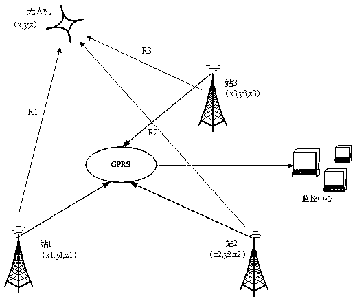
[0019] In one embodiment, the present invention provides an unmanned aerial vehicle target monitoring system based on a mobile phone communication base station tower, and the unmanned aerial vehicle has its corresponding flight characteristics in terms of flight speed, track, and altitude. The UAV detection radar is set up on the tower of the mobile phone communication base station in the city, the target is detected by the FM continuous wave radar, and the detection data is transmitted to the monitoring center through the GPRS wireless communication network, and the monitoring cente...


PUM


Abstract

The invention discloses unmanned, automatic, real-time target monitoring system and method, in which a radar detection system is erected on a city communication base station iron tower and is used formulti-station networking, and is especially suitable for an unmanned plane air object. The unmanned plane target monitoring method comprises the steps of erecting a detection radar on the communication base station iron tower; establishing a monitoring networking; detecting target by means of the detection radar; transmitting the detection data to a monitoring center through wireless communication network; conducting comprehensive processing on the target data and conducting positioning monitoring on the target. The invention is advantageous in that a large-scale monitoring with high precision can be conducted on the unmanned planes in the city, and the detection precision is high and covering scope is wide, and the detection precision and covering scope can be displayed in the city map in a real-time manner in the monitoring center; the high-precision and large-scale monitoring of the unmanned planes can be realized in the city, and city safety can be guaranteed; the detection cost and erecting cost of small-size unmanned planes can be reduced, and comprehensive use of resources can be realized.

Description

technical field [0001] The invention relates to the field of target detection, in particular to an unmanned aerial vehicle target monitoring system and method based on a communication base station iron tower. Background technique [0002] Unmanned aerial vehicles, also known as unmanned aerial vehicles, are unmanned aircraft operated by radio remote control equipment and self-provided program control devices. [0003] Among them, micro-UAVs bring a series of safety problems, such as accidental entry into airports, flight safety, etc., due to their own characteristics such as small size and convenient flight control. Effective monitoring of drones is necessary. The difficulty of real-time monitoring is a long-standing problem in UAV flight supervision. Due to the particularity of the urban environment, the UAV monitoring equipment in the prior art has serious floor occlusions, which greatly restricts the installation conditions of monitoring equipment in cities. For example...

Claims


Application Information

Patent Timeline
Patent Type & Authority Applications(China)
IPC IPC(8): G01S13/42G01S13/34
Inventor 陈俊王胜元孙丽丽华科叶映宇
Owner CEC JINJIANG INFO IND
Learn More