An optical component, a to-can packaged sfp+ module and a cob packaged sfp+ module

An optical component and optical path technology, applied in the coupling of optical waveguides, etc., can solve the problems of large difference of optical components, narrow transition band, difficult film system design, etc., to meet structural requirements, improve coupling efficiency, and reduce size. Effect

Active Publication Date: 2020-01-31
湖北瑞创信达光电有限公司
View PDF6 Cites 0 Cited by
  • Summary
  • Abstract
  • Description
  • Claims
  • Application Information

AI Technical Summary

Problems solved by technology

In the current optical component design, the optical path design tends to realize the function, and the understanding of the current technical level and processing and manufacturing capabilities in the industry is not comprehensive enough, resulting in a large difference between the design effect of the optical component and the actual result.
For example, filter suppliers in the industry require the interval between the passband and cutoff band. If the bandwidth of the passband and cutoff band is relatively large, and their transition band is very narrow, the design of the film system is very difficult, and the transmission of the actual product The efficiency and reflectivity cannot meet the ideal requirements, which in turn imposes additional requirements on the design of optical components or limits the design of optical components

Method used


Image

  • An optical component, a to-can packaged sfp+ module and a cob packaged sfp+ module
  • An optical component, a to-can packaged sfp+ module and a cob packaged sfp+ module
  • An optical component, a to-can packaged sfp+ module and a cob packaged sfp+ module

Examples


specific Embodiment

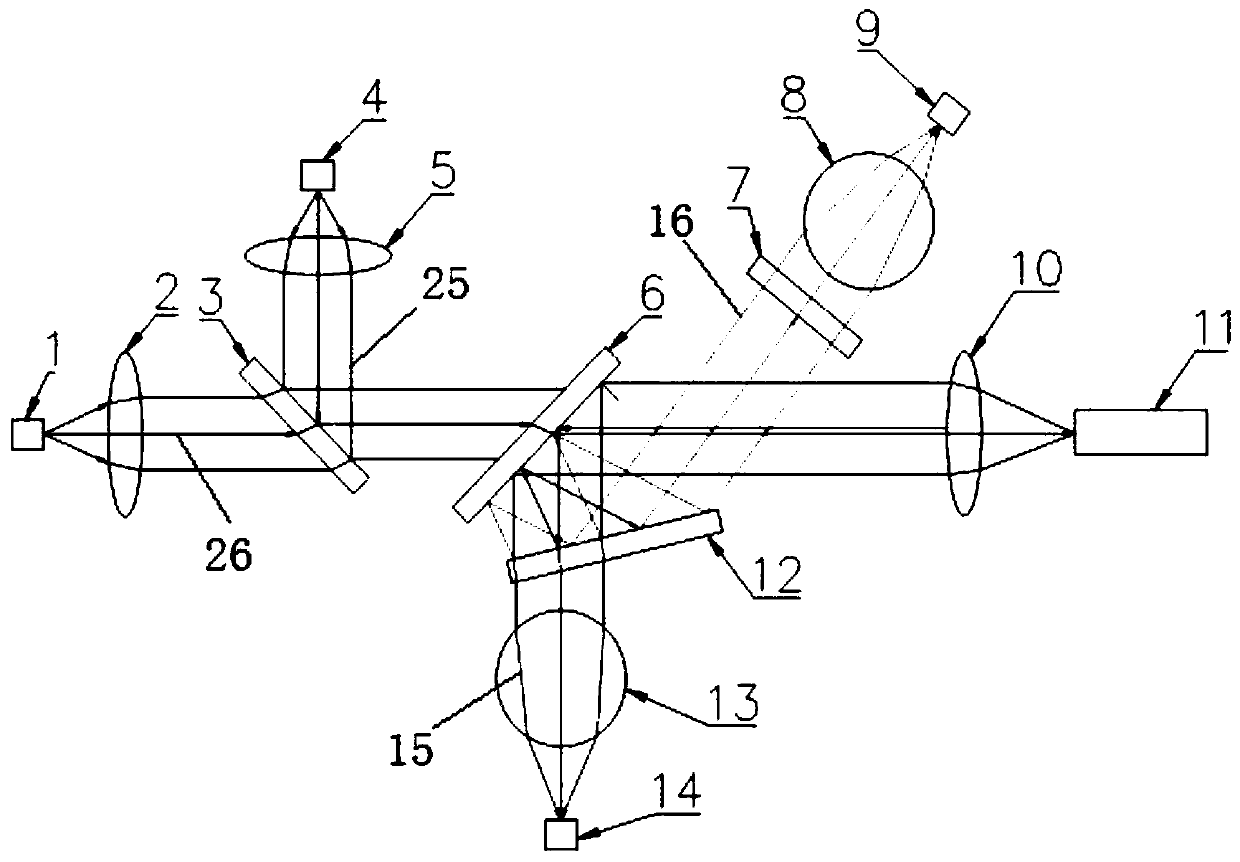
[0029] As an optimization scheme of the embodiment of the present invention, please refer to figure 1 , the angle α between the second filter 12 and the collimated outgoing light from the optical port 11 , 0figure 1 Among them, the angle between the second filter 12 and the horizontal line (that is, the outgoing light of the optical port end 11) is α, and when it is greater than 15°, the second filter 12 cannot completely combine the first uplink light 15 and the second Uplink light 16 splits away. Preferably, the best effect can be achieved when 13° is selected.

[0030] To further optimize the above scheme, please refer to figure 1 , the optical path between the second receiving end 9 and the second filter 12 is provided with a third filter 7, the second uplink light 16 passes through the third filter 7 and enters the second receiving end 9, the third filter 7 and The angle γ=90°+4α between the outgoing lights of the optical ports 11 . The angle between the third filter 7...


PUM


Abstract

The present invention relates to the field of optical components, and provides an optical component, including an optical port end, a first filter and a first receiving end; a first collimating lens is arranged on the optical path between the optical port end and the first filter; A second filter is provided on the optical path between the first filter and the first receiving end, and the first uplink light reflected by the first filter passes through the second filter and enters the first receiving end; the optical assembly also includes a second filter. The second receiving end, the second uplink light is reflected by the second filter and then enters the second receiving end. An optical component of the present invention realizes the complete separation of uplink lights of different wavelengths through the special design of the positions and angles of the first filter, the second filter and the third filter. A TO-CAN packaged SFP+ module and a COB packaged SFP+ module are provided, both of which include the above-mentioned optical component. A TO-CAN-packaged SFP+ module and a COB-packaged SFP+ module of the present invention can both meet the miniaturization requirements of the SFP+ module.

Description

technical field [0001] The invention relates to the field of optical components, in particular to an optical component, a TO-CAN packaged SFP+ module and a COB packaged SFP+ module. Background technique [0002] In order to increase the number of data ports as much as possible in the field of optical fiber communication, optical modules are constantly required to be miniaturized, especially for high-speed, multi-wavelength transmission optical modules, many of which are upgraded from the early XFP package to the SFP+ package. As the core component of the optical module, the structural size of the optical component determines the structural type of the optical module. In the current optical component design, the optical path design tends to realize the function, and the understanding of the current technical level and processing and manufacturing capabilities in the industry is not comprehensive enough, resulting in a large difference between the design effect of the optical ...

Claims


Application Information

Patent Timeline
Patent Type & Authority Patents(China)
IPC IPC(8): G02B6/42
Inventor 周纪承付赟胡云樊志刚
Owner 湖北瑞创信达光电有限公司
Why Eureka
Try Eureka