
Internal combustion engine having spraying device in cylinder tube, and operating method thereof

A technology for internal combustion engines and injection devices, which is applied in the direction of combustion engines, fuel injection devices, engine components, etc., and can solve the problems that are not suitable for being arranged in the area of ​​the cylinder bore in a concave manner

Active Publication Date: 2018-01-12
FORD GLOBAL TECH LLC
View PDF6 Cites 0 Cited by
  • Summary
  • Abstract
  • Description
  • Claims
  • Application Information

AI Technical Summary

Problems solved by technology

For example, the concepts described above generally relate to injection nozzles arranged in the cylinder head and protruding into the combustion chamber, and are not suitable for being arranged in a concave manner in the region of the cylinder bore, that is to say for being located in a recess, ie Injection device for the removal or reduction of fuel or coking residues located in the dead volume

Method used


Image

  • Internal combustion engine having spraying device in cylinder tube, and operating method thereof
  • Internal combustion engine having spraying device in cylinder tube, and operating method thereof
  • Internal combustion engine having spraying device in cylinder tube, and operating method thereof

Examples


Embodiment Construction

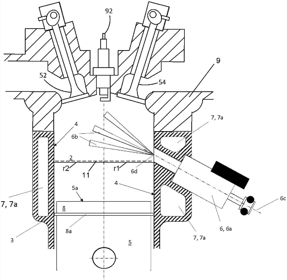
[0044] Mixture preparation in direct injection engines presents challenges because of the negative effects caused by any wall wetting. If the fuel spray hits the cylinder liner, the oil is potentially diluted (eg, the fuel can collect and then drain to an oil pan where the oil can be diluted). Excessive soot formation can occur if the fuel spray strikes the piston. One difficulty with centrally mounted fuel injectors in the cylinder head is the alignment of the flow directions of the fuel and air. The lack of relative motion between the two fuel and air causes a long duration of evaporation, a high penetration length of the spray and thus a high probability of wall wetting.

[0045] Injectors on the side of the cylinder head, so-called side-mounted direct injectors, do not take full advantage of side injection due to the injector's proximity to the intake valve and have limited freedom in positioning due to retraction in the cylinder head .

[0046] According to the embodim...


PUM


Abstract

The invention relates to an internal combustion engine having a spraying device in cylinder tube, and an operating method thereof. The invention also relates to a fuel spraying device positioned in acylinder tube. A cylinder comprises a piston top, a cylinder tube defining a combustion chamber, and a combustion chamber formed by the cylinder tube and a cylinder cover. The cylinder includes a spraying device which is positioned in the cylinder tube for directing introducing fuel to the combustion chamber. The spraying device is provided with at least one opening. During the spraying process, the at least one opening is triggered to introduce the fuel to the combustion chamber. The spraying device and the cylinder tube are terminated at the side face of the combustion chamber.

Description

[0001] Related applications [0002] This application claims priority from German Patent Application No. 102016212084.0 filed on July 4, 2016. The entire contents of the above application are incorporated herein by reference in their entirety for all purposes. technical field [0003] The present disclosure relates to a direct injection internal combustion engine. Background technique [0004] The internal combustion engine has a cylinder block and at least one cylinder head, which are connected to each other to form a cylinder and its combustion chamber. The cylinder block is typically used as the upper crankcase half for the mounting of the crankshaft and for housing the pistons and cylinder sleeves for each cylinder. The piston can also be directly mounted and guided in the bore of the cylinder block without the need for a cylinder sleeve as an intermediate element. In the context of this disclosure, both the cylinder sleeve and the orifice come under the expression "c...

Claims


Application Information

Patent Timeline
Patent Type & Authority Applications(China)
IPC IPC(8): F02B15/00F02B17/00
CPCF02M45/08F02M61/14F02M61/1806
Inventor A·布罗伊尔T·洛伦茨M·科霍斯罗维H·H·鲁兰德
Owner FORD GLOBAL TECH LLC
Learn More