
Gasification system and its use

A gasification system and gasification reactor technology, applied in the field of gasification systems, can solve problems such as easy damage, and achieve the effects of easy handling and avoiding heat exchange surfaces

Active Publication Date: 2012-11-14
AIR PROD & CHEM INC
View PDF11 Cites 0 Cited by
  • Summary
  • Abstract
  • Description
  • Claims
  • Application Information

AI Technical Summary

Problems solved by technology

Another problem is that the heat exchange surfaces are even more easily damaged by fouling e.g. by raw materials with high alkali content

Method used


Image

  • Gasification system and its use
  • Gasification system and its use
  • Gasification system and its use

Examples


Embodiment Construction

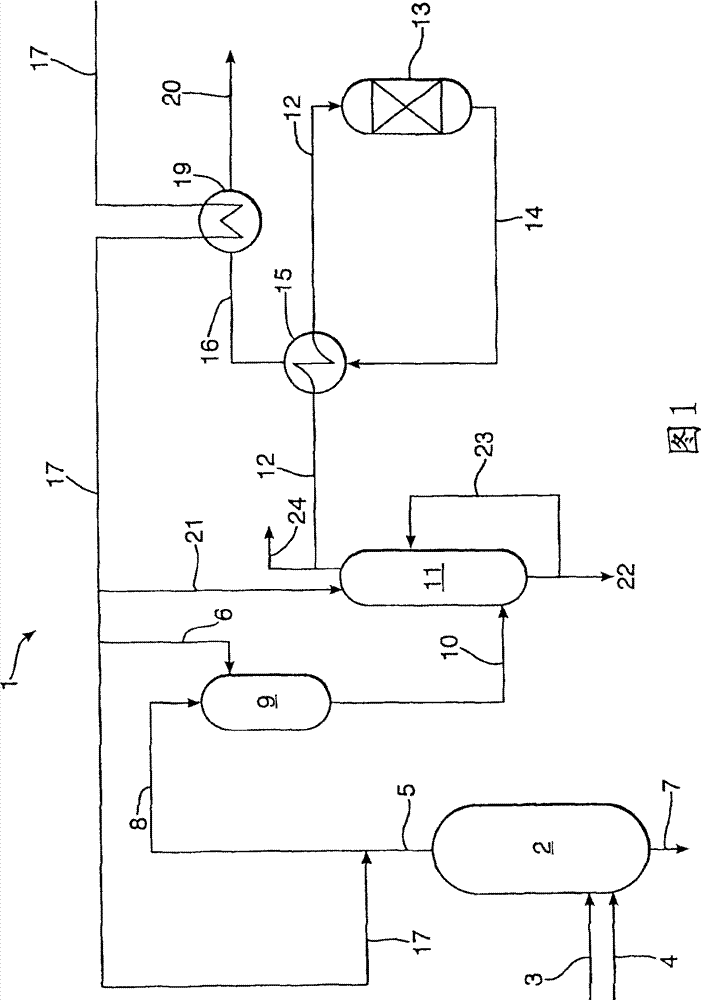
[0022] The gasification reactor of the invention is suitable for producing a mixture comprising carbon monoxide and hydrogen by partial oxidation of a solid hydrocarbonaceous feed in the gasification reactor of the invention or in the system of the invention. In the process, a solid hydrocarbonaceous feed is partially oxidized with an oxygen-containing gas in a gasification chamber to form an upwardly moving gas mixture having a temperature of 1200-1800°C, preferably 1400-1800°C. The mixture is preferably cooled in a first cooling step. The gas is preferably further cooled to below 500°C in a separate cooling vessel.

[0023] The solid hydrocarbonaceous feed is partially oxidized with an oxygen-containing gas. Preferred hydrocarbonaceous feedstocks are solid high carbonaceous feedstocks, more preferably consisting essentially (ie >90wt%) of naturally occurring coal or synthetic (petroleum) coke, most preferably coal. Suitable coals include lignite, bituminous, sub-bituminous...


PUM


Abstract

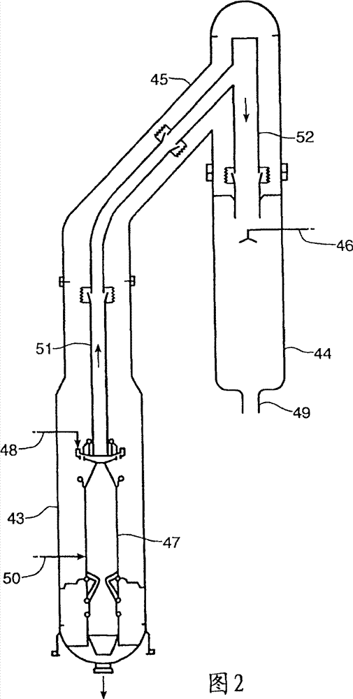
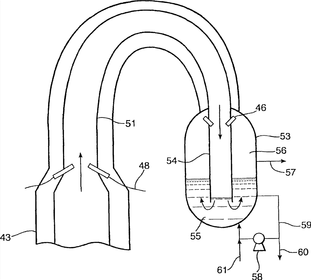
The present invention relates to a gasification system that comprises a gasification reactor (43) and a synthesis gas cooling vessel (44), and use thereof. The gasification reactor (43) comprises a pressure shell for maintaining a pressure higher than atmospheric pressure; a slag bath located in a lower part of the pressure shell; and a gasifier wall arranged inside the pressure shell for defining a gasification chamber (47). The synthesis gas can be formed during the operation of gasification chamber, a lower open part of the gasifier wall which is in fluid communication with the slag bath and an open upper end of the gasifier wall which is in fluid communication with the synthesis gas cooling vessel (44) via a connecting conduit (51). The synthesis gas cooling vessel (44) comprises an inlet for hot synthesis gas; an outlet (49) for cooled synthesis gas; and means (46) to directly contact liquid water with the hot synthesis gas as formed in the gasification reactor in use.

Description

technical field [0001] The present invention relates to an improved gasification system for producing a mixture comprising carbon monoxide and hydrogen from a hydrocarbonaceous stream using an oxygen-containing stream. The gasification system includes a gasification reactor and a syngas cooling vessel. The invention also relates to a method for preparing a mixture comprising carbon monoxide and hydrogen in the system of the invention. Background technique [0002] Methods for producing synthesis gas are known from practice. An example of a process for producing synthesis gas is described in EP-A-400740. Generally, a hydrocarbonaceous stream such as coal, lignite, peat, wood, coke, soot or other gaseous, Partial combustion of liquid or solid fuels or mixtures thereof, whereby synthesis gas (CO and H 2 ), CO 2 and slag. The slag formed during the partial combustion falls and is discharged through an outlet located at or near the bottom of the reactor. [0003] The hot p...

Claims


Application Information

Patent Timeline
Patent Type & Authority Patents(China)
IPC IPC(8): C10J3/48C10J3/78C10J3/82
CPCC10K1/10B01D53/79Y02E20/18C10K1/16C10J3/485C10J2200/09C10J2300/1846B01D53/002C10K1/101C10J2300/093C10J3/78C10J3/48C10J3/82C10K1/08C10J2300/0959
Inventor R·E·梵登伯格F·G·梵东恩T·P·冯科萨克-格洛夫切夫斯基H·J·梵德普莱格P·L·苏德维尔德
Owner AIR PROD & CHEM INC
Learn More