Ultra wide band low radar cross section microstrip antenna

A radar cross section and microstrip antenna technology, applied in the field of antennas, can solve problems such as narrow cross-section bandwidth, and achieve the effect of increasing and reducing bandwidth, reducing electromagnetic interference, and reducing radar cross-section.

Active Publication Date: 2018-01-12
XIDIAN UNIV +1
View PDF5 Cites 6 Cited by
  • Summary
  • Abstract
  • Description
  • Claims
  • Application Information

AI Technical Summary

Problems solved by technology

[0005] The purpose of the present invention is to overcome the defects in the above-mentioned prior art, and propose a microstrip antenna with ultra-wideband and low radar cross section, which is used to solve the technical problem of reducing the narrow bandwidth of the radar cross section of the existing microstrip antenna

Method used


Image

  • Ultra wide band low radar cross section microstrip antenna
  • Ultra wide band low radar cross section microstrip antenna
  • Ultra wide band low radar cross section microstrip antenna

Examples


Embodiment 1

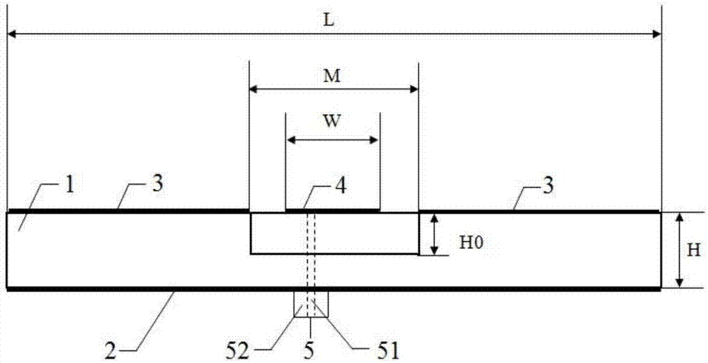
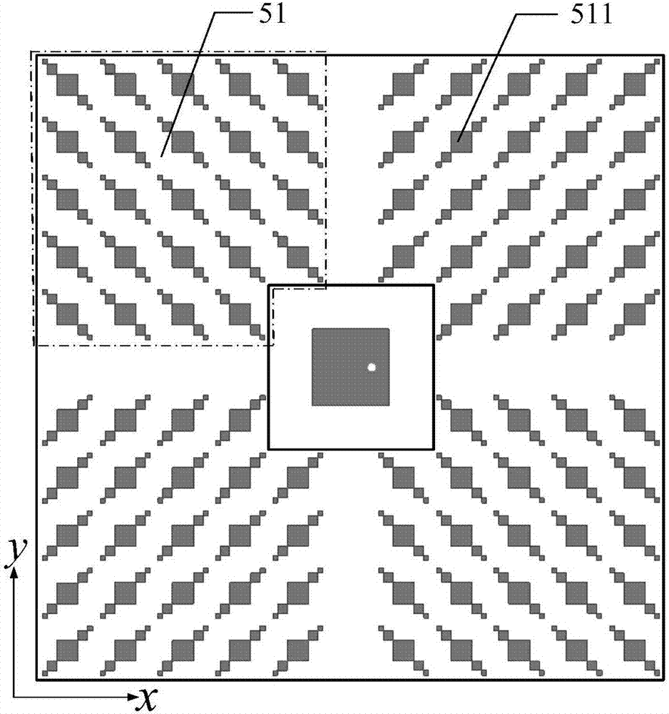
[0025] refer to figure 1 , a microstrip antenna with ultra-wideband and low radar cross-section, including a dielectric substrate 1, a metal floor 2, a polarization conversion surface 3, a radiation unit 4 and a coaxial joint 5; the dielectric constant of the dielectric substrate 1 is 2.62, and the side length L =65mm square plate, its thickness H=2mm; the metal floor 2 is printed on the lower surface of the dielectric substrate 1, and the shape and size of the metal floor 2 are the same as the dielectric substrate 1; the polarization conversion surface 3 is printed on the dielectric substrate 1 The upper surface of the dielectric substrate 1 is provided with a rectangular cavity with a square cross section at the upper center of the dielectric substrate 1, the side length of the square is M=17mm, the cavity height H0=1mm, the rectangular cavity coincides with the longitudinal central axis of the dielectric substrate 2, Thereby improving the resonant frequency point of the mic...

Embodiment 2

[0029] This embodiment has the same structure as Embodiment 1, only some parameters have been adjusted:

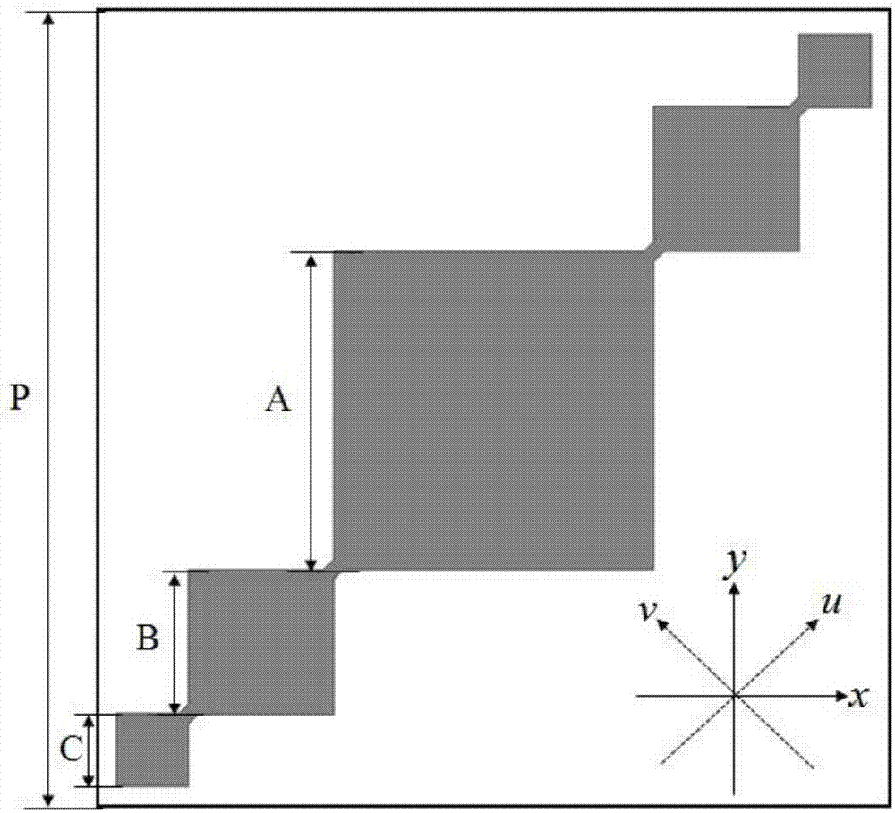
[0030] The side length M of the cross section of the rectangular cavity is 12 mm, and the middle side length A of the decreasing fractal unit 311 is 2.0 mm.

Embodiment 3

[0032] This embodiment has the same structure as Embodiment 1, only some parameters have been adjusted:

[0033] The side length M of the cross section of the rectangular cavity is 20 mm, and the middle side length A of the decreasing fractal unit 311 is 2.2 mm.

[0034] Below in conjunction with simulation experiment, technical effect of the present invention is described further:

[0035] 1. Simulation conditions and content:

[0036] 1.1 Using the commercial simulation software HFSS_15.0 to simulate the reflection coefficient and polarization conversion rate of the decreasing fractal unit in the above example 1 in the range of 8GHz-34GHz, the results are as follows Figure 4 shown.

[0037] 1.2 Use the commercial simulation software HFSS_15.0 to simulate and calculate the co-polar reflection coefficient of the decreasing fractal unit in the above example 1 in the range of 8GHz-34GHz, the results are as follows Figure 5 shown.

[0038] 1.3 Utilize the commercial simulat...


PUM


Abstract

The invention provides an ultra wide band low radar cross section microstrip antenna and aims to solve a technical problem of narrow bandwidth of a microstrip antenna reduction radar cross section inthe prior art. The microstrip antenna comprises a medium substrate, a metal floor, a polarized conversion surface, a radiation unit and a coaxial connector, wherein the metal floor is printed at a lower surface of the medium substrate, the polarized conversion surface is printed at an upper surface of the medium substrate, the center position of an upper side of the medium substrate is provided with a rectangular chamber, an upper portion of the chamber is provided with the radiation unit fixed with an output end of the coaxial connector, the polarized conversion surface is composed of four polarized conversion unit sets, each polarized conversion unit set comprises multiple decreasing fractal units, and arrangement direction difference of decreasing fractal units of the adjacent polarizedconversion unit sets is 900. The microstrip antenna is advantaged in that the ultra wide band decrement microstrip antenna radar cross section has stable performance, and the microstrip antenna can be applied to antenna systems with the complex electromagnetic environment to reduce electromagnetic interference among antennas in a wide band.

Description

technical field [0001] The invention belongs to the technical field of antennas, and relates to a microstrip antenna with ultra-wideband and low radar section, which can be used in antenna systems with complex electromagnetic environments to reduce electromagnetic interference between antennas in a wide frequency band. Background technique [0002] In today's communication field, the signal transmitting and receiving system is the most important part of the entire communication platform, and the antenna is the core part of the system. With the development of wireless technology, the electromagnetic environment in which antennas are located is becoming more and more complex, and mutual interference between antennas has become an important factor affecting signal transmission and reception. The radiation characteristics of an antenna determine its ability to send and receive electromagnetic waves, and its scattering characteristics have an important impact on its electromagnet...

Claims


Application Information

Patent Timeline
Patent Type & Authority Applications(China)
IPC IPC(8): H01Q1/38H01Q1/50H01Q1/52H01Q15/24H01Q19/00
Inventor 洪涛谷越赵强邢文博姜文龚书喜刘英
Owner XIDIAN UNIV
Why Eureka
Try Eureka