
Tower type desulfurization and denitrification device and desulfurization and denitrification method

A desulfurization, denitrification and tower technology is applied in the field of flue gas purification and treatment, which can solve the problems of great harm to human body and poor effect, and achieve the effect of high safety, strong practicability and improving purification effect.

Pending Publication Date: 2018-01-16
安徽金森源环保工程有限公司
View PDF0 Cites 7 Cited by
  • Summary
  • Abstract
  • Description
  • Claims
  • Application Information

AI Technical Summary

Problems solved by technology

[0002] Smoke is a mixture of gas and smoke, which is the main cause of air pollution in residential areas. The composition of smoke is very complex, including water vapor, SO2, N2, O2, CO, CO2, hydrocarbons, and nitrogen oxides. Smoke and dust Including fuel ash, coal particles, oil droplets and high-temperature cracking products, etc. Therefore, the pollution of flue gas to the environment is the compound pollution of various poisons. The harm of smoke to the human body is related to the size of the particles. Flying dust with a diameter of less than 10 microns, especially 1-2.5 microns, is the most harmful. Flue gas desulfurization and denitrification technology is a boiler flue gas purification technology used in the chemical industry where nitrogen oxides and sulfur oxides are generated. Nitrogen oxides 1. Sulfur oxides are one of the main sources of air pollution. The existing tower-type desulfurization and denitrification devices usually use adsorbents to remove single and desulfurization. The effect is not good, and the adsorbents need to be collected in the tower. more harmful to the human body

Method used


Image

  • Tower type desulfurization and denitrification device and desulfurization and denitrification method

Examples


Embodiment Construction

[0019] The following will clearly and completely describe the technical solutions in the embodiments of the present invention with reference to the accompanying drawings in the embodiments of the present invention. Obviously, the described embodiments are only some, not all, embodiments of the present invention. Based on the embodiments of the present invention, all other embodiments obtained by persons of ordinary skill in the art without making creative efforts belong to the protection scope of the present invention.

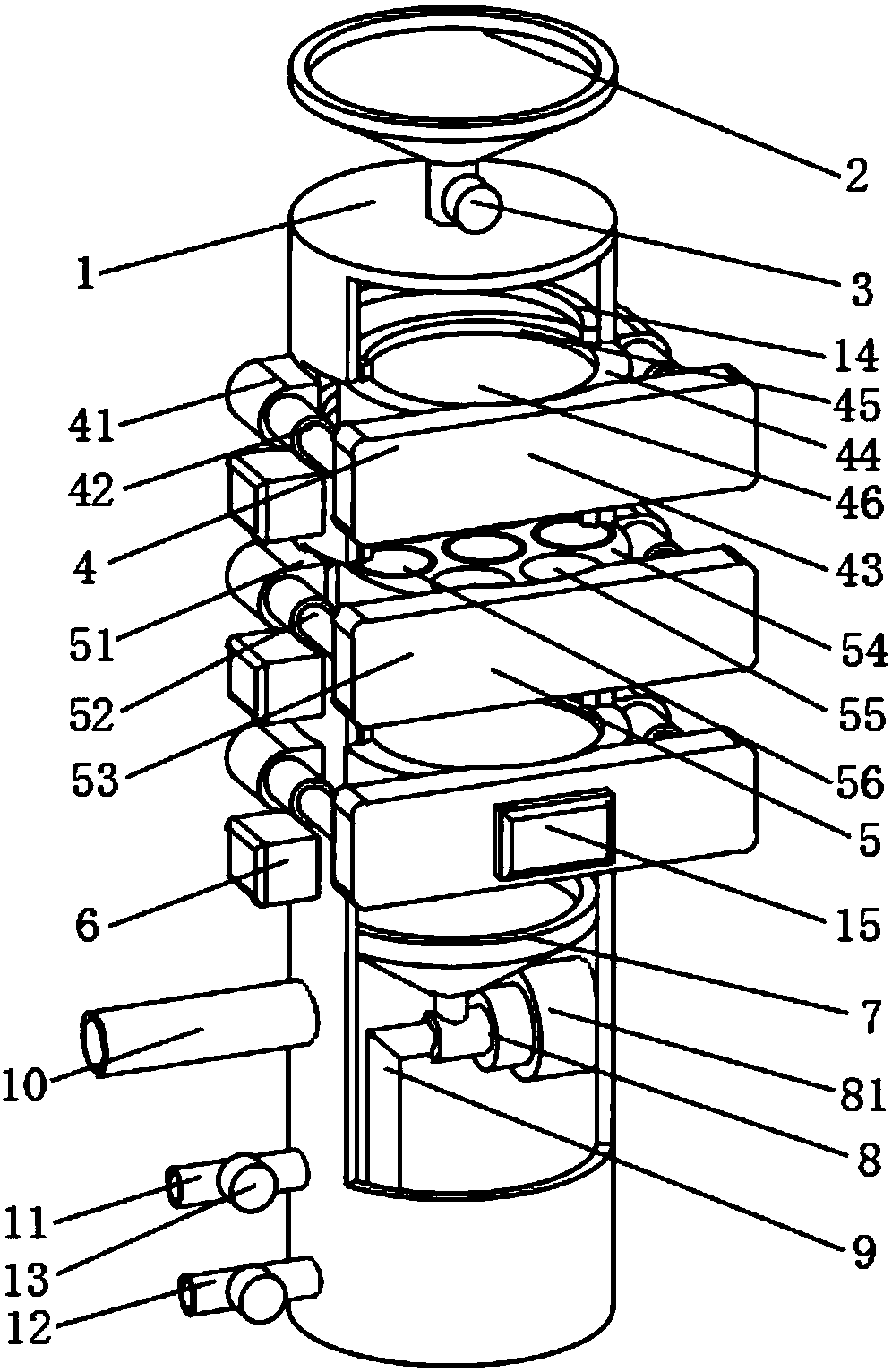
[0020] see figure 1, the present invention provides a technical solution: a tower-type desulfurization and denitrification device, including an outer shell 1, the upper surface of the outer shell 1 is provided with an air intake funnel 2, so that the external flue gas enters the inside of the outer shell 1, and the air intake The side lower end of the funnel 2 is provided with a first electromagnetic valve 3, and the side upper end and the side middle part of ...


PUM


Abstract

The invention discloses a tower type desulfurization and denitrification device and a desulfurization and denitrification method. The tower type desulfurization and denitrification device comprises anouter shell, wherein an air inlet funnel is arranged on the upper surface of the outer shell, a first electromagnetic valve is arranged at the lower end of the lateral side of the air inlet funnel, adsorption devices are arranged at the upper end of the lateral side of the outer shell and in the middle of the lateral side of the outer shell, a catalyzing device is arranged on the lateral side ofthe outer shell and between the two adsorption devices, and sealing rings are arranged on the internal lateral side corresponding to the adsorption devices and the catalyzing device of the outer shell. The tower type desulfurization and denitrification device and the desulfurization and denitrification method can sequentially absorb sulfur oxide and nitrogen oxide and further can detect componentsof gas in the outer shell, activated carbon fiber cloth and a honeycomb-like catalyst can be conveniently replaced from the outside in time, damage to an operator is avoided, safety is high, a desulfurization and denitrification efficiency and a flue gas purifying effect further can be improved, and practicability is improved.

Description

technical field [0001] The invention relates to the technical field of flue gas purification and treatment, in particular to a tower-type desulfurization and denitrification device and a desulfurization and denitrification method. Background technique [0002] Smoke is a mixture of gas and smoke, which is the main cause of air pollution in residential areas. The composition of smoke is very complex, including water vapor, SO2, N2, O2, CO, CO2, hydrocarbons, and nitrogen oxides. Smoke and dust Including fuel ash, coal particles, oil droplets and high-temperature cracking products, etc. Therefore, the pollution of flue gas to the environment is the compound pollution of various poisons. The harm of smoke to the human body is related to the size of the particles. Flying dust with a diameter of less than 10 microns, especially 1-2.5 microns, is the most harmful. Flue gas desulfurization and denitrification technology is a boiler flue gas purification technology used in the chemi...

Claims


Application Information

Patent Timeline
IPC IPC(8): B01D53/86B01D53/56B01D53/02
Inventor 张殿坤
Owner 安徽金森源环保工程有限公司
Features
  • Generate Ideas
  • Intellectual Property
  • Life Sciences
  • Materials
  • Tech Scout
  • Unparalleled Data Quality
  • Higher Quality Content
  • 60% Fewer Hallucinations
Learn More