Induction coil and equipment used for eliminating residual stress of engine valve, and method

A technology of engine valves and induction coils, which is applied in the field of induction coils to eliminate the residual stress of engine valves, and can solve problems such as difficulty in accurately controlling the tempering temperature, uneven temperature of the bottom surface of the valve head, and inability to measure the temperature of the bottom surface of the valve, etc., to achieve The effect of eliminating valve residual stress, eliminating residual stress, and saving manufacturing materials

Inactive Publication Date: 2018-01-16
HUAI JI DENG YUE VALVE CO LTD
View PDF4 Cites 2 Cited by
  • Summary
  • Abstract
  • Description
  • Claims
  • Application Information

AI Technical Summary

Problems solved by technology

In the prior art, an annular planar coil similar to a mosquito coil is often used as an induction coil to heat the bottom surface of the valve to eliminate the residual stress of the valve. The induction coil and the engine valve are located on the same center line, but according to Lenz's law, the annular The magnetic induction lines of the planar coil are distributed in a ring shape, which overlaps with the rotation direction of the bottom surface of the engine valve, which will cause uneven temperature on the bottom surface of the valve head, which will easily cause local overheating, and then lead to an overheated area on the bottom surface of the valve. Reduced the pass rate of the product
In addition, when the annular planar coil is used, since the annular planar coil blocks the bottom surface of the valve during operation, it is impossible to measure the temperature of the bottom surface of the valve during infrared temperature measurement, and the bottom surface of the valve is the part with the highest temperature during heating, which is easy to cause Due to inaccurate infrared temperature measurement, it is difficult to accurately grasp the tempering temperature, and it is easy to cause the metallographic failure of the bottom surface of the valve, resulting in a low product qualification rate

Method used


Image

  • Induction coil and equipment used for eliminating residual stress of engine valve, and method
  • Induction coil and equipment used for eliminating residual stress of engine valve, and method

Examples


Embodiment

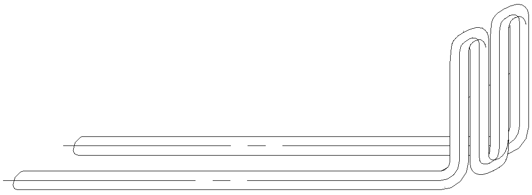
[0028] This embodiment provides an induction coil for eliminating the residual stress of the engine valve, and the induction coil is V-shaped, U-shaped or wave-shaped. It is preferably W-shaped, such as figure 1 shown.

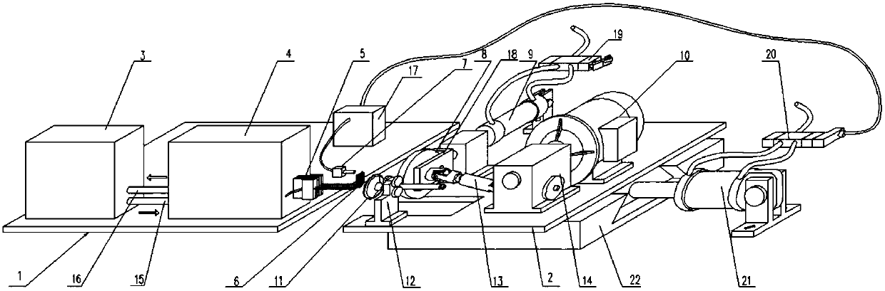
[0029] Such as figure 2 As shown, the present embodiment also provides a device using the above-mentioned induction coil, including a frame, a workbench, a heating device, a fixture and a control device, the workbench includes a fixed workbench 1 and a movable workbench 2, and the fixed workbench The table 1 is fixedly installed on the frame, and the movable workbench 2 is installed on the frame through the feeding device. The heating device is installed on the fixed workbench 1 and includes an induction heating power supply 4 and an induction coil 6. The induction heating device The coil 6 is installed on the output end of the induction heating power supply 4 and is located in front of the clamp fixing tool; the clamp is used to clamp the engine valve and ...


PUM


Abstract

The invention discloses an induction coil and equipment used for eliminating the residual stress of an engine valve. The induction coil is of a V shape, a U shape or a wave type. The invention also discloses equipment used for eliminating the residual stress of the engine valve. The equipment comprises a rack, a workbench, a heating device and a fixture, wherein the workbench comprises a fixed workbench and a movable workbench; the fixed workbench is fixedly installed on the rack; the movable workbench is installed on the rack through a feeding device. The equipment is characterized in that the heating device is installed on the fixed workbench and comprises an induction heating power supply and the induction coil, wherein the induction coil is installed on the output side of the inductionheating power supply and is positioned in front of a fixture fixing tool; the fixture is used for clamping the engine valve and is arranged on a position near the induction coil on the movable workbench. The induction coil and the equipment have the advantages of evenness in heating, low distressing temperature and high product percent of pass, and residual stress generated after the valve is subjected to surfacing can be stably eliminated.

Description

technical field [0001] The invention relates to the field of valve processing, in particular to an induction coil, equipment and method for eliminating the residual stress of an engine valve. Background technique [0002] Overlay welding technology is a maintenance technology that uses welding to strengthen the surface of mechanical parts. Using this technology can change the chemical composition and structure of the surface of the part, improve its performance, and prolong the service life of the part. It has important economic value. In order to improve the service life of the engine valve sealing surface (that is, the cone surface or disc cone surface), it is necessary to surfacing hard alloy at the end of the engine valve disc, but the surfacing welding technology will inevitably bring surfacing welding residual stress, surfacing welding The superposition of stress generated by residual stress and external load can easily lead to excessive stress in local areas, thus red...

Claims


Application Information

Patent Timeline
Patent Type & Authority Applications(China)
IPC IPC(8): C21D1/42C21D9/00
CPCC21D1/42C21D9/00Y02P10/20Y02P10/25
Inventor 王飞华莫东强邓剑雄廉绍玲黄立勋郭潮赵伟明陈永兴黎志彦卢啟棠邓继韶黄志钢李东平
Owner HUAI JI DENG YUE VALVE CO LTD
Why Eureka
Try Eureka