FPGA-based dual-system control device and method for brushless DC motor

A brushed DC motor and control device technology, applied in the direction of electronic commutation motor control, single motor speed/torque control, control system, etc., can solve the problems of threatening safety, inaccurate Hall signals, and affecting production efficiency, etc., to achieve Guaranteed motor and improved efficiency

Inactive Publication Date: 2018-01-16
HARBIN UNIV OF SCI & TECH
View PDF4 Cites 8 Cited by
  • Summary
  • Abstract
  • Description
  • Claims
  • Application Information

AI Technical Summary

Problems solved by technology

Among them, the position brushless DC motor control has become the mainstream control method, and the Hall sensor has become the choice of the mainstream sensor. However, when the Hall sensor has a measurement error or fails, the Hall signal will be inaccurat

Method used


Image

  • FPGA-based dual-system control device and method for brushless DC motor
  • FPGA-based dual-system control device and method for brushless DC motor
  • FPGA-based dual-system control device and method for brushless DC motor

Examples


Example Embodiment

Specific embodiment one

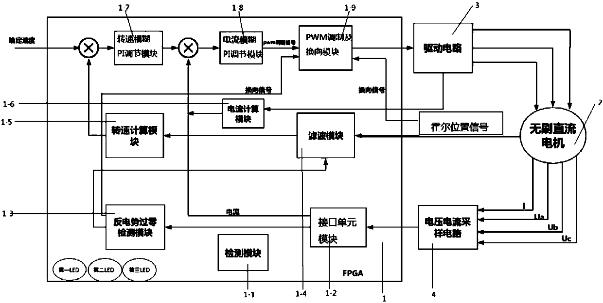
[0026] A dual-system brushless DC motor control device based on FPGA, such as figure 1 As shown, it includes an FPGA1, a brushless DC motor 2, a drive circuit 3, a voltage and current sampling circuit 4, a first LED indicator, a second LED indicator, and a third LED indicator; the FPGA1 includes a detection module 1-1, Interface unit module 1-2, back EMF zero-crossing detection module 1-3, filter module 1-4, speed calculation module 1-5, current calculation module 1-6, speed fuzzy PI adjustment module 1-7, current fuzzy PI adjustment Modules 1-8 and PWM modulation and commutation modules 1-9; the signal passes through speed fuzzy PI adjustment module 1-7, current fuzzy PI adjustment module 1-8, PWM modulation and commutation module 1-9 and drive circuit in turn 3. Reach the brushless DC motor 2; the drive circuit 3 sends signals through the current calculation module 1-6 to the current fuzzy PI adjustment module 1-8; the brushless DC motor 2 sends signal...

Example Embodiment

Specific embodiment two

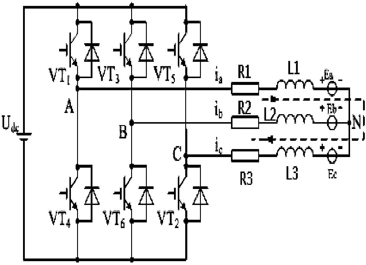
[0031] Said FPGA-based dual-system brushless DC motor control device, such as figure 2 As shown, the drive circuit 3 includes a power supply Udc, a transistor VT1, a transistor VT2, a transistor VT3, a transistor VT4, a transistor VT5, a transistor VT6, a resistor R1, a resistor R2, a resistor R3, an inductor L1, an inductor L2, an inductor L3 , Voltage source Ea, voltage source Eb, and voltage source Ec; the Udc is connected to VT1 and VT4, the VT1 and VT4, VT3 and VT6, VT5 and VT2 are connected in parallel, and point A between the VT1 and VT4 is connected to R1 and L1 in turn And Ea, the VT3 and VT6 set B points R2, L2 and Eb in turn, the VT5 and VT2 intermediary set C points to connect R3, L3 and Ec in turn, and the A, B and C are connected to the point N.

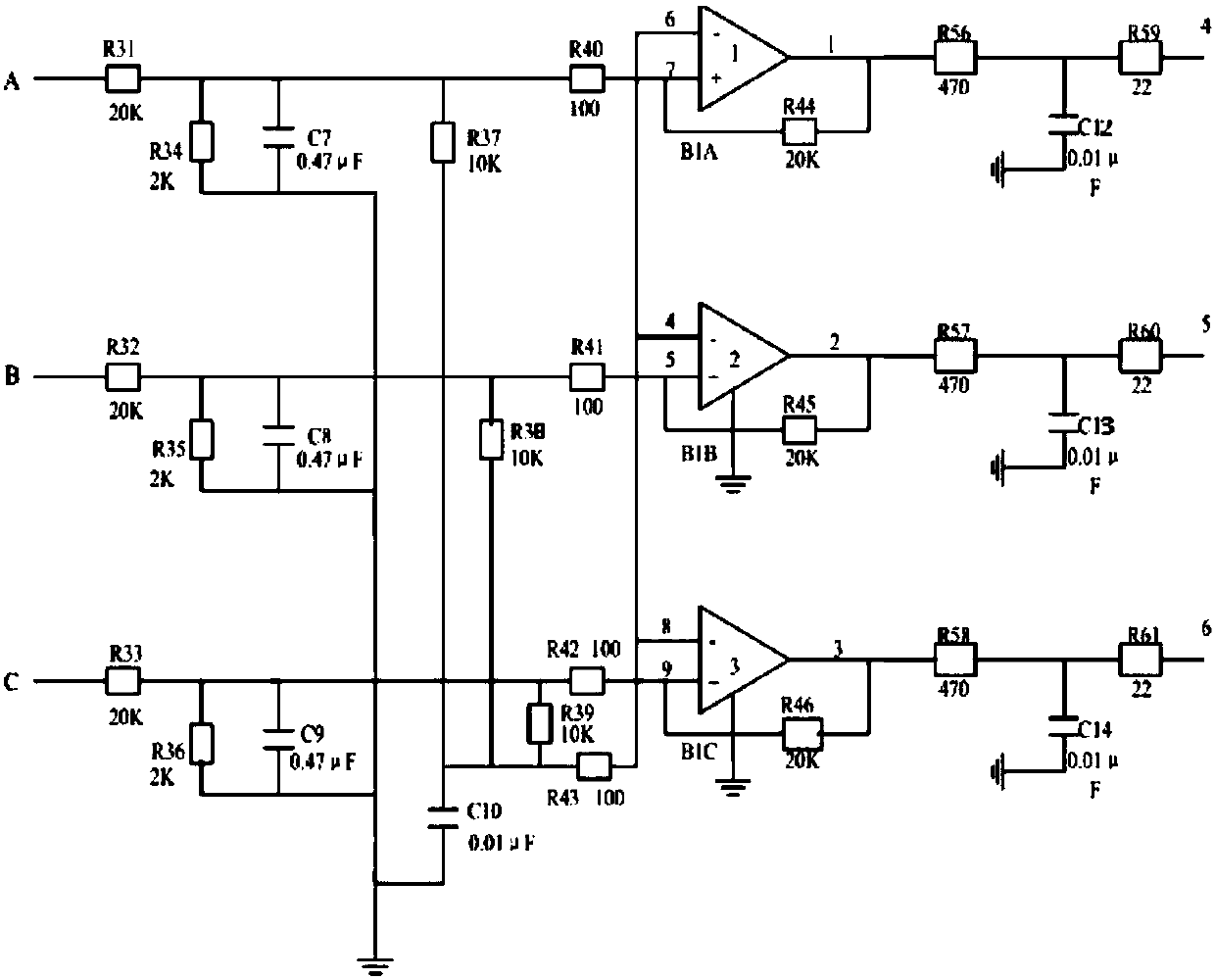
[0032] Said FPGA-based dual-system brushless DC motor control device, such as image 3 As shown, the back-EMF zero-crossing detection module 1-3 includes resistor R31, resistor R32, resistor R33, r...

Example Embodiment

Specific embodiment three

[0034] An FPGA-based dual-system brushless DC motor control method implemented on the FPGA-based dual-system brushless DC motor control device includes the following steps:

[0035] Step a. Using FPGA1 as the main control chip, download the position sensor system and the position sensorless system to FPGA1;

[0036] Step b. Start the brushless DC motor 2, the Hall sensor and the back-EMF position sensor are started at the same time, and the position sensor system and the position sensor system perform Hall position signal and voltage and current acquisition respectively;

[0037] Step c. First select the Hall sensor to control the brushless DC motor 2. The voltage and current sampling circuit 4 collects the three-phase voltage and current signals of the brushless DC motor 2 and transmits them to the interface unit module 1-2, and detects the module 1 at the same time -1 Detection of Hall position signal;

[0038] If the Hall position signal is not abnormal, ...


PUM


Abstract

The invention discloses an FPGA-based dual-system control device and method for a brushless DC motor and belongs to the field of motor control. The device comprises an FPGA, a brushless DC motor, a drive circuit, a voltage and current sampling circuit, an indicator light LED1, an indicator light LED2 and an indicator light LED3, wherein the FPGA is connected with the brushless DC motor through thedrive circuit and the voltage and current sampling circuit separately; the indicator light LED1, the indicator light LED2 and the indicator light LED3 are arranged on the FPGA; and the brushless DC motor is provided with a hall sensor. The method comprises the steps as follows: a position sensor system and a position-sensorless system are adopted; when a detection module detects that an error occurs in a hall signal, a back electromotive force zero-crossing system runs for motor control and the brushless DC motor continues to run; and when the detection module detects that two sets of controlsystems for the brushless DC motor go wrong, the LED lights on the FPGA send out corresponding indication signals and timely prompt the staff to deal, thereby ensuring that the motor can safely and efficiently run. The problem of a failure of the hall sensor is effectively solved.

Description

Technical field [0001] The invention relates to an FPGA-based dual-system brushless DC motor control device and method, which belong to the field of motor control. Background technique [0002] Brushless DC motors have the advantages of long life, low noise, simple structure, excellent mechanical properties, small size, light weight, high reliability, no sparks, strong overload capacity, and high control accuracy. They are widely used in industry, aerospace, etc. And other fields. Among them, the position brushless DC motor control has become the mainstream control method, and the Hall sensor has become the choice of the mainstream sensor. However, when the Hall sensor has a measurement error or malfunctions, the Hall signal will be inaccurate at this time. Brushless DC motors will have problems such as commutation errors, affecting production efficiency and even threatening safety. How to solve the countermeasures when Hall fails is the focus and difficulty of current research....

Claims


Application Information

Patent Timeline
IPC IPC(8): H02P6/00H02P6/08H02P6/16H02P6/182
Inventor 温嘉斌赵红阳刘子宁
Owner HARBIN UNIV OF SCI & TECH
Why Eureka
Try Eureka