Vacuum drum filtering system

A filtration system and vacuum drum technology, applied in filtration and separation, moving filter element filters, separation methods, etc., can solve the problems of short service life, high-density accumulation of sediments, low work efficiency, etc., to improve the scope of application, High filtration efficiency, easy disassembly and cleaning

Inactive Publication Date: 2018-01-19
WENZHOU JINGGONG BEER COMPLETE EQUIP
View PDF3 Cites 1 Cited by
  • Summary
  • Abstract
  • Description
  • Claims
  • Application Information

AI Technical Summary

Problems solved by technology

[0004] Therefore, the technical problem to be solved by the present invention is to overcome the disadvantages that the drum filter surface of the existing vacuum drum filter equipment is easy to cause high-density accumulation of sediment, low work efficiency and short service life.

Method used


Image

  • Vacuum drum filtering system
  • Vacuum drum filtering system
  • Vacuum drum filtering system

Examples


Embodiment 1

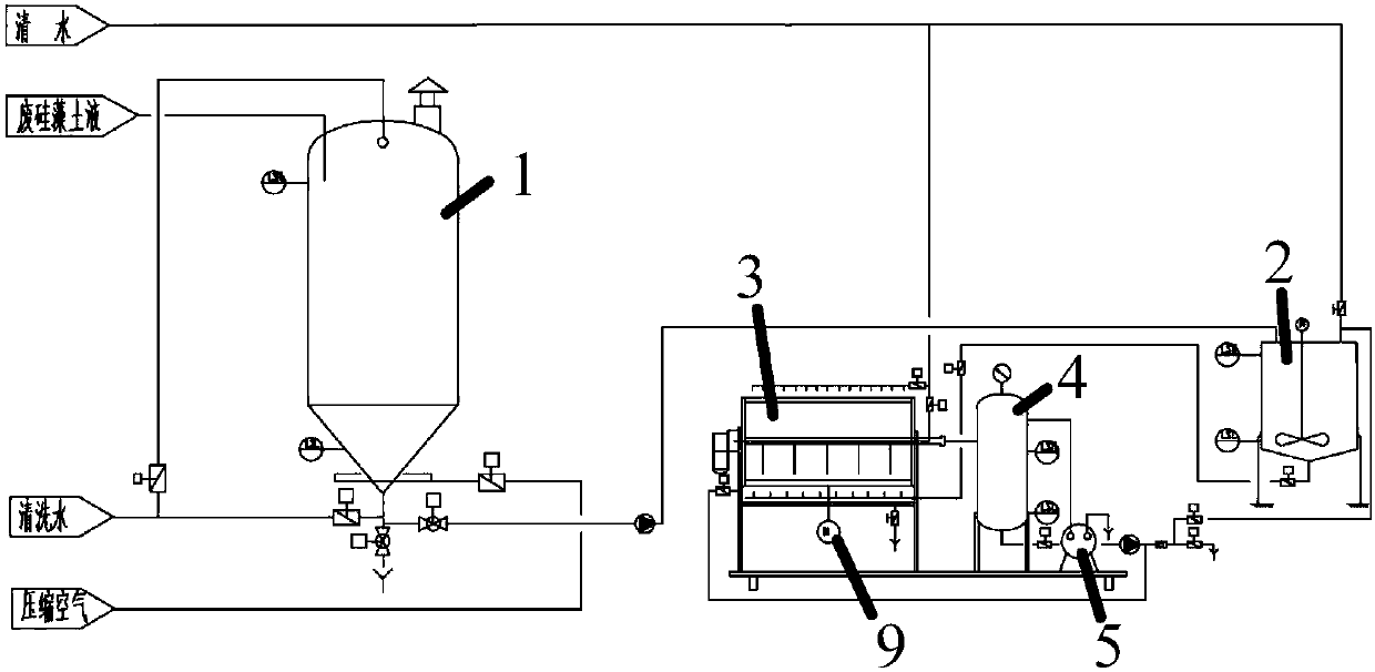
[0030] A vacuum drum filtration system is described as figure 1 As shown, it includes a waste diatomite storage tank 1, a mixing tank 2, a vacuum drum filter 3, a raw material temporary storage cylinder 4 and a vacuum pump 5 connected in sequence, and it is characterized in that the vacuum drum filter 3 includes:

[0031] The bracket 6 is arranged in the filter tank 7;

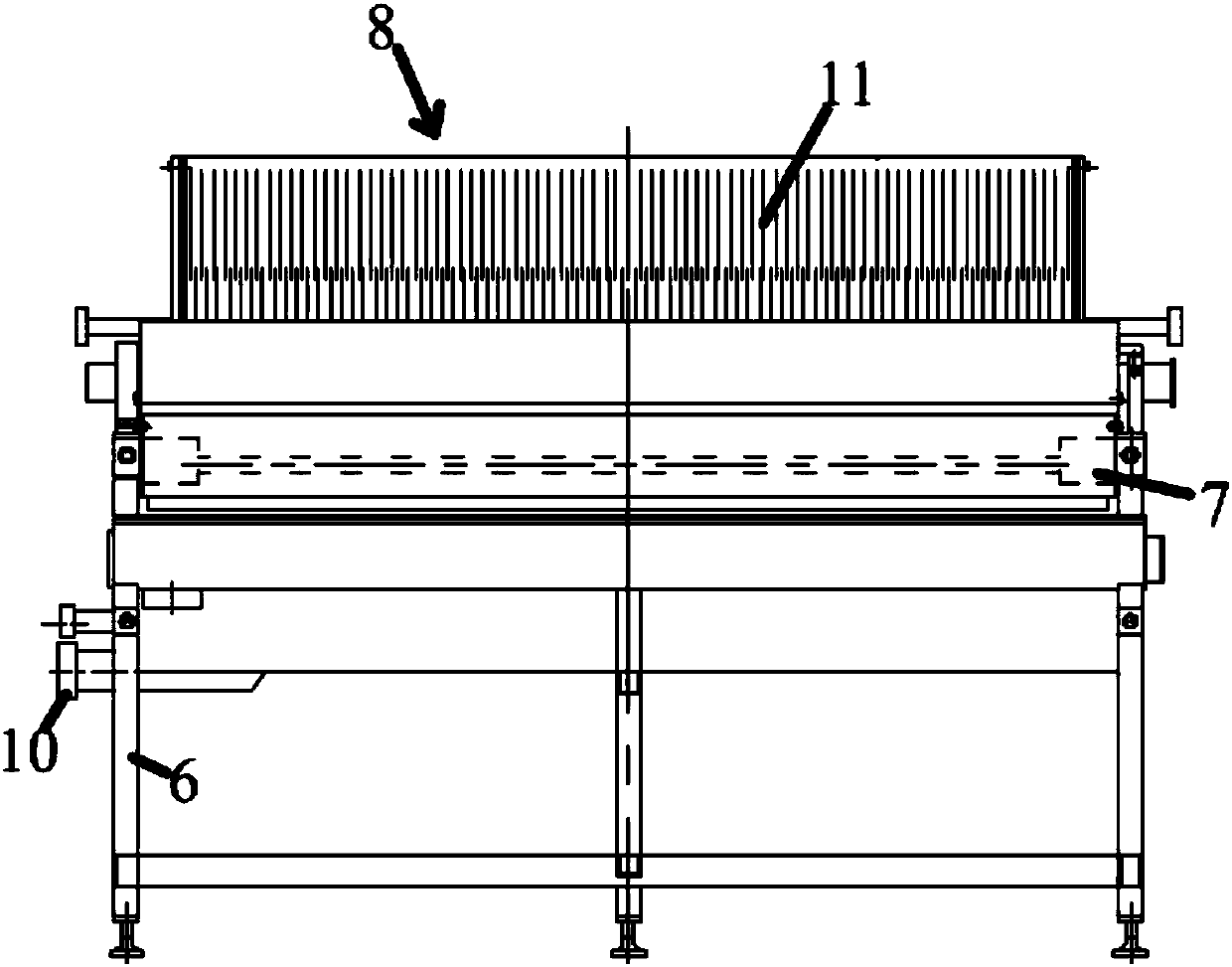
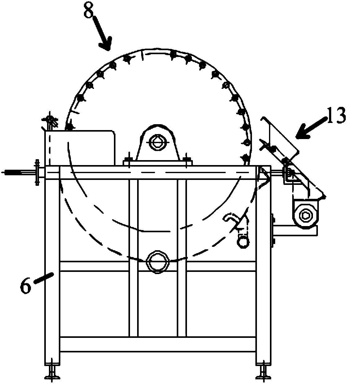
[0032] The drum 8 is connected with the power mechanism 9 through transmission, and is rotatably installed on the support 6. The drum 8 is respectively provided with a sewage discharge pipe 10 connected with the filter tank 7 and a discharge pipe 10 connected with the raw material temporary storage cylinder 4. Material tube;

[0033] Such as figure 2 , image 3 and Figure 4 As shown, the filter screen 11 is arranged in the drum 8, and the filter screen 11 includes a number of wedge-shaped metal wires and a number of fixing ribs, and the fixing ribs are arranged in a circular array to form a columnar fixi...

Embodiment 2

[0041] A vacuum drum filtration system is described as figure 1 As shown, it includes a waste diatomite storage tank 1, a mixing tank 2, a vacuum drum filter 3, a raw material temporary storage cylinder 4 and a vacuum pump 5 connected in sequence, and it is characterized in that the vacuum drum filter 3 includes:

[0042] The bracket 6 is arranged in the filter tank 7;

[0043] The drum 8 is connected with the power mechanism 9 through transmission, and is installed on the support 6 for rotation. The drum 8 is respectively provided with a sewage discharge pipe 10 connected with the filter tank 7 and a discharge pipe 10 connected with the temporary storage cylinder 4 for raw materials. Material tube;

[0044] Such as figure 2 , image 3 and Figure 4 As shown, the filter screen 11 is arranged in the drum 8, and the filter screen 11 includes a number of wedge-shaped metal wires and a number of fixing ribs, and the fixing ribs are arranged in a circular array to form a colum...


PUM


Abstract

The invention relates to a vacuum drum filtering system. The vacuum drum filtering system comprises a waste diatomite storage tank, a mixing tank, a vacuum drum filter, a raw material temporary storage vat and a vacuum pump which are sequentially connected, wherein the vacuum drum filter comprises a bracket, a revolving drum and a filter net, and the bracket is arranged in filter tank; the revolving drum is in transmission connection with the power mechanism and is rotatably arranged on the bracket, a sewage discharging pipe connected with the filter tank is arranged on the revolving drum, anda discharging pipe connected with the raw material temporary storage vat is arranged on the revolving drum; and the filter net is arranged in the revolving drum and comprises a plurality of metal wires with wedge-shaped cross sections and a plurality of fixed ribs, the fixed ribs are annularly arrayed to form a columnar fixed frame, and the metal wires are arranged on the columnar fixed frame atcertain intervals. According to the vacuum drum filtering system, the problems that the valid filtering gaps in the surface of a filter pipe on a filtering surface of an existing drum are few, the filter flow of a unit area is low, the high-density accumulation of precipitates is easily caused due to the strong obstruction property, and therefore, vacuum drum filtering equipment is low in workingefficiency and short in service life are solved.

Description

technical field [0001] The invention relates to the technical field of filters, in particular to a vacuum drum filter system. Background technique [0002] Vacuum drum filter belongs to light equipment for dehydration and recovery of diatomite, and is mainly used for drying treatment of waste diatomite after filtration of beer and syrup. The equipment is driven by the reducer to rotate the filter drum continuously and at a constant speed. Using the vacuum pressure difference formed by the vacuum pump, the material flowing through the filter tank is sucked and filtered through the distributor in the filter drum, and the water in the material liquid is continuously filtered. The solid material (such as diatomaceous earth) is evenly adsorbed on the outer surface of the drum to form a filter cake layer. When the filter cake layer reaches a certain thickness, it can be discharged by adjusting the scraper plate in the discharge area. When it reaches the position of cutting the ca...

Claims


Application Information

Patent Timeline
Patent Type & Authority Applications(China)
IPC IPC(8): B01D33/067B01D33/46B01D33/76B01D33/80
Inventor 吴光伟
Owner WENZHOU JINGGONG BEER COMPLETE EQUIP
Why Eureka
Try Eureka